Method for assisted beam selection in radiation therapy planning

a radiation therapy and beam selection technology, applied in radiation therapy, radiation therapy, x-ray/gamma-ray/particle irradiation therapy, etc., can solve the problems of speeding up the search, insufficient favor in clinical applications, and expensive computer time, and achieve the effect of easy incorporation

Inactive Publication Date: 2006-04-11
LLACER JORGE
View PDF11 Cites 104 Cited by
  • Summary
  • Abstract
  • Description
  • Claims
  • Application Information

AI Technical Summary

Benefits of technology

[0039]Another advantage of the invention is that the nature of the calculations to be carried out and of the interactive displays to be generated is such that they can be easily incorporated in commercial software treatment plans.
[0040]Yet another advantage of the invention is that its use does not rely on complex mathematical operations that exclude the judgment of the Radiation Oncologist and, in fact, it relies on that judgment to make a final selection of beam angles or arcs, guided by computer graphics that are usually already incorporated into available commercial radiation treatment planning software packages.
[0041]Yet another alternative advantage of the invention is that the resulting optimal plane or planes can form a subset of all possible delivery orientations from a source that can travel over the surface of a sphere and that smaller subset can be used as input to an automatic beam selection algorithm, if desirable.
[0042]Other objects, advantages and novel features will be set forth in part in the following portions of the specification, wherein the detailed description is for the purpose of fully disclosing the preferred embodiment of the invention, without placing limitations thereon.

Problems solved by technology

In general, the methods shown yield better optimizations than some reference set of beams, although they are very expensive in computer time and have not found sufficient favor in clinical applications.
2179–2193, returns to the use of a genetic algorithm specifically for coplanar beams, using a methodology that allows the algorithm to search in parallel for different objectives, resulting in a speed up of the search.
They still report many hours of computation for relatively complex therapy cases.
The method of Pugachev and Xing, however, suffers from the severe limitation that is only applicable to therapy with coplanar beams, that is, beams that originate in a radiation source that can move along the perimeter of a circle.
The extension of Pugachev and Xing's method to non-coplanar beams is prohibitive, as would be the case with all the other selection methods reviewed above.
The extremely high increase in the number of possible candidate beam orientations in going from a circular set of source positions to a spherical one results in an inordinate increase in computation time.
The main cause of difficulty with all the attempts at solving the beam selection problem is the overly ambitious goal that has been set, that of selecting automatically all the beams that should be used in the optimization of a particular clinical case.
Those methods, however, do not use make good use of the capabilities of current computational techniques in Computer Vision, which can provide more accurate and complete information about the nature of the boundaries between a PTV and any adjacent OARs.

Method used


Image

  • Method for assisted beam selection in radiation therapy planning
  • Method for assisted beam selection in radiation therapy planning
  • Method for assisted beam selection in radiation therapy planning

Examples


example

[0077]In order to illustrate and clarify the preferred embodiment of the invention, the optimization of an IMRT radiation treatment plan for the mathematical phantom of FIG. 4 will be described in detail. Initially, a standard optimization will be described, followed by a second optimization using the assisted beam orientation selection method of the present invention.

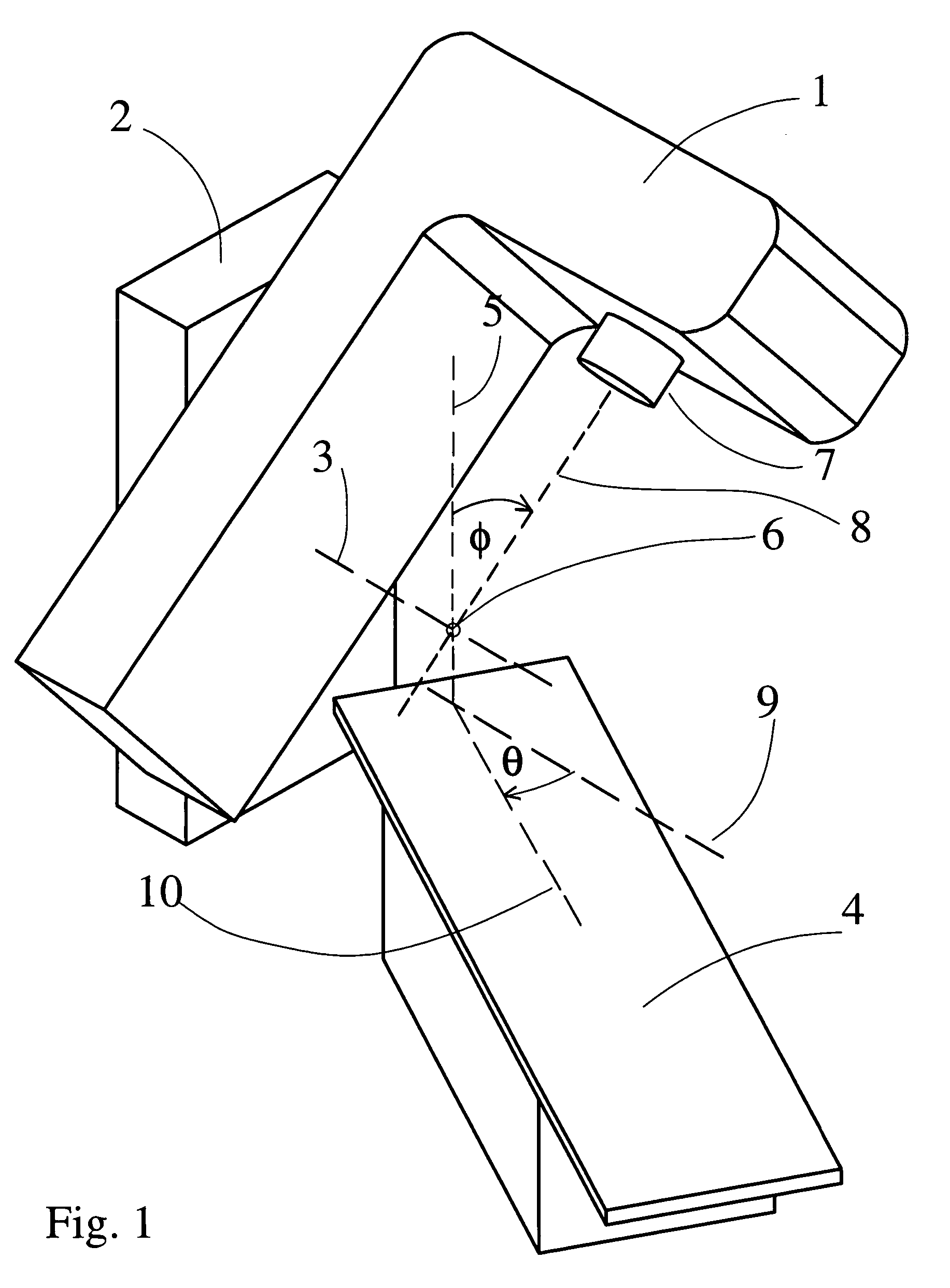
[0078]From the work of T. Bortfeld and W. Schlegel in “Optimization of beam orientations in radiation therapy: some theoretical considerations”, Physics in Medicine and Biology, Vol. 38, (1993), pp. 291–304 and that of S. Webb in “Optimizing the planning of intensity-modulated radiotherapy”, Physics in Medicine and Biology, Vol. 39, (1994), pp. 2229–2246, which has been followed well by the Radiation Oncology profession in all the intervening years, a nine-beam co-planar treatment plan with equal angular spacing will be devised for the phantom of FIG. 4 placed on the patient table 4 with the phantom centroid 18 placed ...


PUM


Abstract

A method to assist in the selection of optimum beam orientations for radiation therapy when a planning treatment volume (PTV) is adjacent to one or more organs-at-risk (OARs). A mathematical analysis of the boundaries between the PTV and OARs allows the definition of a continuum of pairs of gantry and table angles whose beam orientations have planes that are essentially parallel to those boundaries, and can, therefore, separate the PTV from the OARs when a multi-leaf collimator is used in the therapy. The Radiation Oncologist can then select one or more pairs of gantry and table angles from the continuum as input to a beam optimization step. The selected angles can deliver highly uniform dose to the PTV, while minimizing the radiation dose to the OARs.

Description

BACKGROUND OF THE INVENTION[0001]1. Field of the Invention[0002]The invention relates to radiation therapy planning for the treatment of tumors or for stereotactic radiosurgery and more particularly to assist in the selection of optimum beam orientations for that therapy.[0003]2. Description of Prior Art[0004]The goal of radiation therapy is the accurate delivery of a radiation dose to tumors or other abnormal tissues in the human body to cause their obliteration, while keeping the dose received by sensitive organs and / or normal tissues to a tolerable minimum. Four main methods of radiation delivery are in use at the present time: Conformal, Intensity Modulated, Dynamic Arc and Tomotherapy. The Conformal method uses a relatively small number of radiation beams, each having a perimeter that conforms to the external shape of the abnormal tissues, as seen from the direction of the incoming beam. In Intensity Modulated Radiation Treatment (IMRT), each of the conformal beams is broken in...

Claims


Application Information

Patent Timeline
Patent Type & Authority Patents(United States)
IPC IPC(8): A61N5/10
CPCA61N5/1031A61N5/1042
Inventor LLACER, JORGE
Owner LLACER JORGE
Why Eureka
Try Eureka