Particle beam irradiation system

Inactive Publication Date: 2008-03-06
SIEMENS AG
View PDF6 Cites 102 Cited by
  • Summary
  • Abstract
  • Description
  • Claims
  • Application Information

AI Technical Summary

Benefits of technology

[0007]A system having a unique setup for treating an ocular tumor a light source and a removable cone having a collimator is disclosed. The cone can be easily mounted and un-mounted to a nozzle of either a gantry (rotatable beam outlet) or a more usual fixed beam outlet. The cone includes a cone input and a cone output. The cone input re

Problems solved by technology

In order to properly focus these dedicated beam lines, complex equipment for beam shaping and collimation as well as target fixation is utilized.
However, this set up does not allow the radiation of small fields with sufficient precision for ey

Method used


Image

  • Particle beam irradiation system
  • Particle beam irradiation system
  • Particle beam irradiation system

Examples


Embodiment Construction

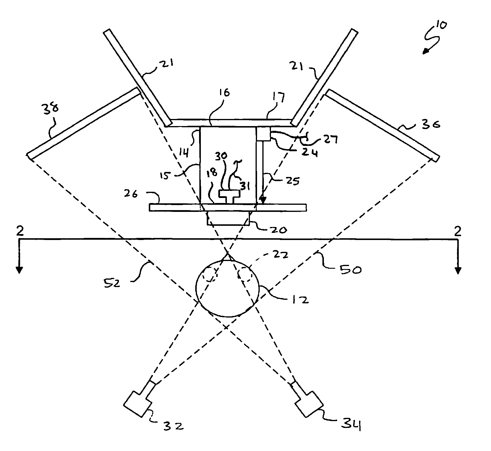
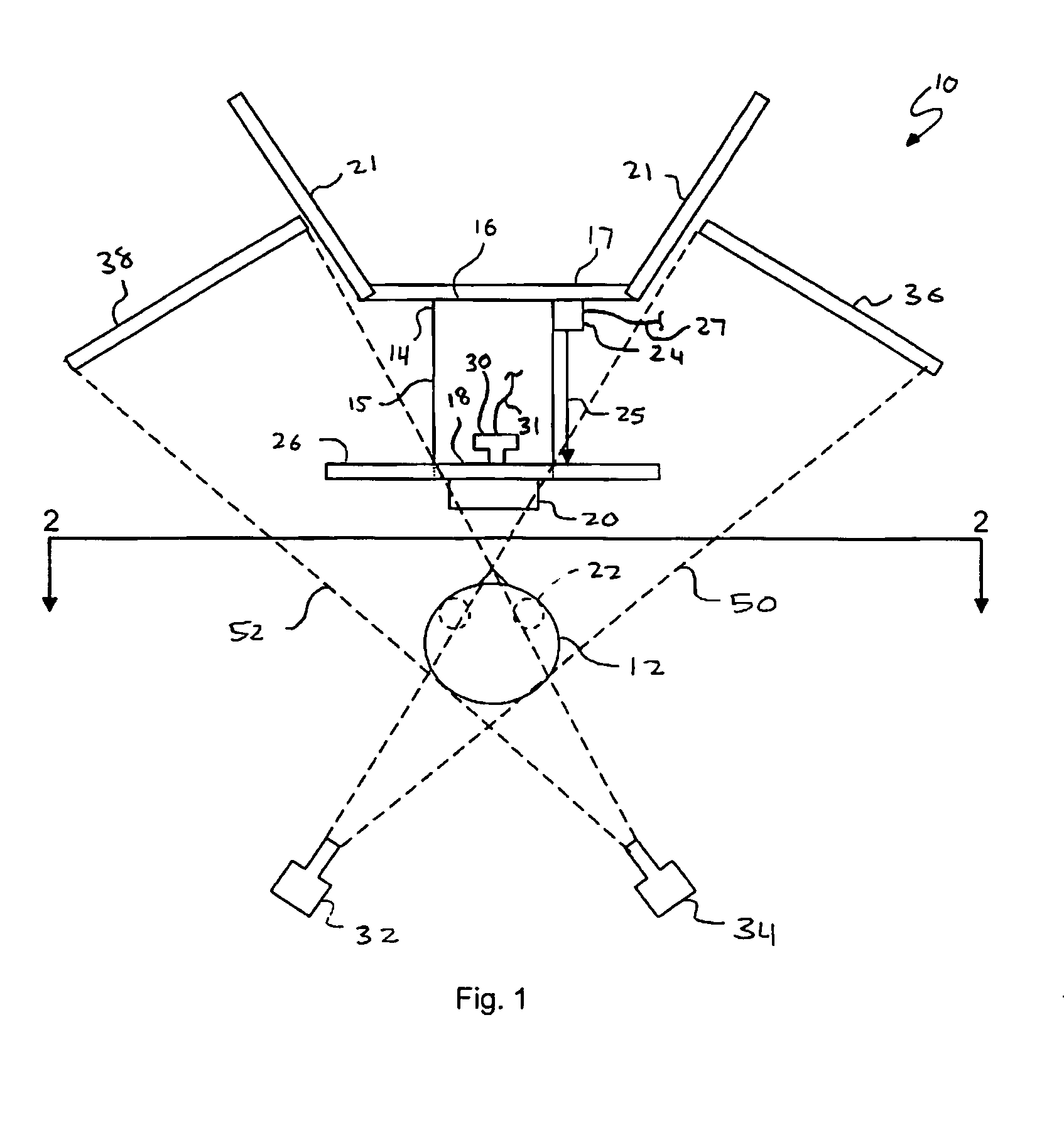
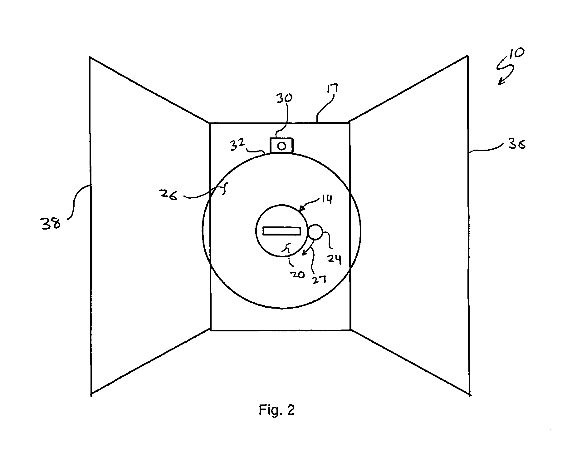
[0013]Referring to FIGS. 1 and 2, a system 10 for treating an ocular tumor or other ocular condition of a patient 12 is shown. The system 10 includes a cone 14 having an elongated body portion 15 with an input 16 and an output 18 located at opposing ends of the body portion 15. The cone 14 may be made of aluminum, plexiglass or any suitable material. As will be described later, the input 16 of the cone 14 receives radiation for treating the ocular tumor of the patient 12. This radiation is transferred from the input 16 of the cone 14 to the output 18 of the cone 14.

[0014]The radiation used for treating the ocular tumor of the patient 12 originates from a radiation source (not shown). This radiation is then fed into a treatment nozzle 21. In order to provide this radiation from the treatment nozzle 21, the input 16 of the cone 14 is attached to the treatment nozzle 21. Generally, the input 16 of the cone 14 is a hole. A base plate 17 fixedly attaches to the input 16 of the cone 14. T...


PUM


Abstract

A system for treating an ocular tumor having a cone, a collimator, a light source and a camera is disclosed. The cone includes a cone input and a cone output and is capable of being mounted and un-mounted to a treatment nozzle. The cone input receives radiation from the treatment nozzle for the treatment of the ocular tumor. The collimator is coupled to the cone output and configured to collimate radiation received by the cone output. This collimated radiation is directed to the patient having the ocular tumor. The light source coupled to the cone. The light source is configured to provide a focusing point of the eye of the patient. A camera coupled to the cone monitors the position of the eye of the patient.

Description

BACKGROUND[0001]I. Technical Field[0002]The present embodiments generally relate to particle beam irradiation systems for treating ocular tumors.[0003]II. Background[0004]Particle therapy systems for the treatment of ocular tumors use dedicated beam lines for the irradiation of the ocular tumor. Irregularly shaped tumors with awkward configurations near critical structures are well suited for proton beam therapy. Protons have a physical advantage over gamma rays and x-rays when it comes to sparing normal tissues. Protons deposit most of their radiation energy in what is known as the Bragg peak, which occurs at the point of greatest penetration of the protons in tissue. The exact depth to which protons penetrate, and at which the Bragg peak occurs, is dependent on the energy of the proton beam. This energy can be very precisely controlled to place the Bragg peak within a tumor or other tissues that are targeted to receive the radiation dose. Because the protons are absorbed at this p...

Claims


Application Information

Patent Timeline
IPC IPC(8): A61N5/10A61B6/00G01N23/00G21K1/12H05G1/60
CPCA61F9/00A61N2005/1087A61N5/1049A61N5/1017
Inventor GROZINGER, SVEN OLIVERMOYERS, MICHAEL FARLEY
Owner SIEMENS AG
Why Eureka
Try Eureka