X-ray protection device

a protection device and x-ray technology, applied in the direction of x-ray tube vessels/containers, diagnostics, applications, etc., can solve the problems of scattered x-ray incident to the collimator, reflect and scatter, etc., to prevent the effect of reducing the area and reducing the amount of scattered/reflected

Active Publication Date: 2005-04-14
PHILIPS DIGITAL MAMMOGRAPHY SWEDEN
View PDF17 Cites 111 Cited by
  • Summary
  • Abstract
  • Description
  • Claims
  • Application Information

AI Technical Summary

Benefits of technology

[0010] Thus, the main object of the present invention according to preferred embodiments is to reduce or eliminate the amount of the scattered/reflected in x-ray apparatus, especially for mammography apparatus having a collimator unit, mainly a vertically adjustable collimator unit, arranged between the breast and the x-ray source. Another object according to a preferred embodiment is to prevent reduction of the area that the x-rays hit the examined object because of the shielding arrangement. Moreover, the shielding

Problems solved by technology

However, some of the x-ray incident to t

Method used


Image

  • X-ray protection device
  • X-ray protection device
  • X-ray protection device

Examples


second embodiment

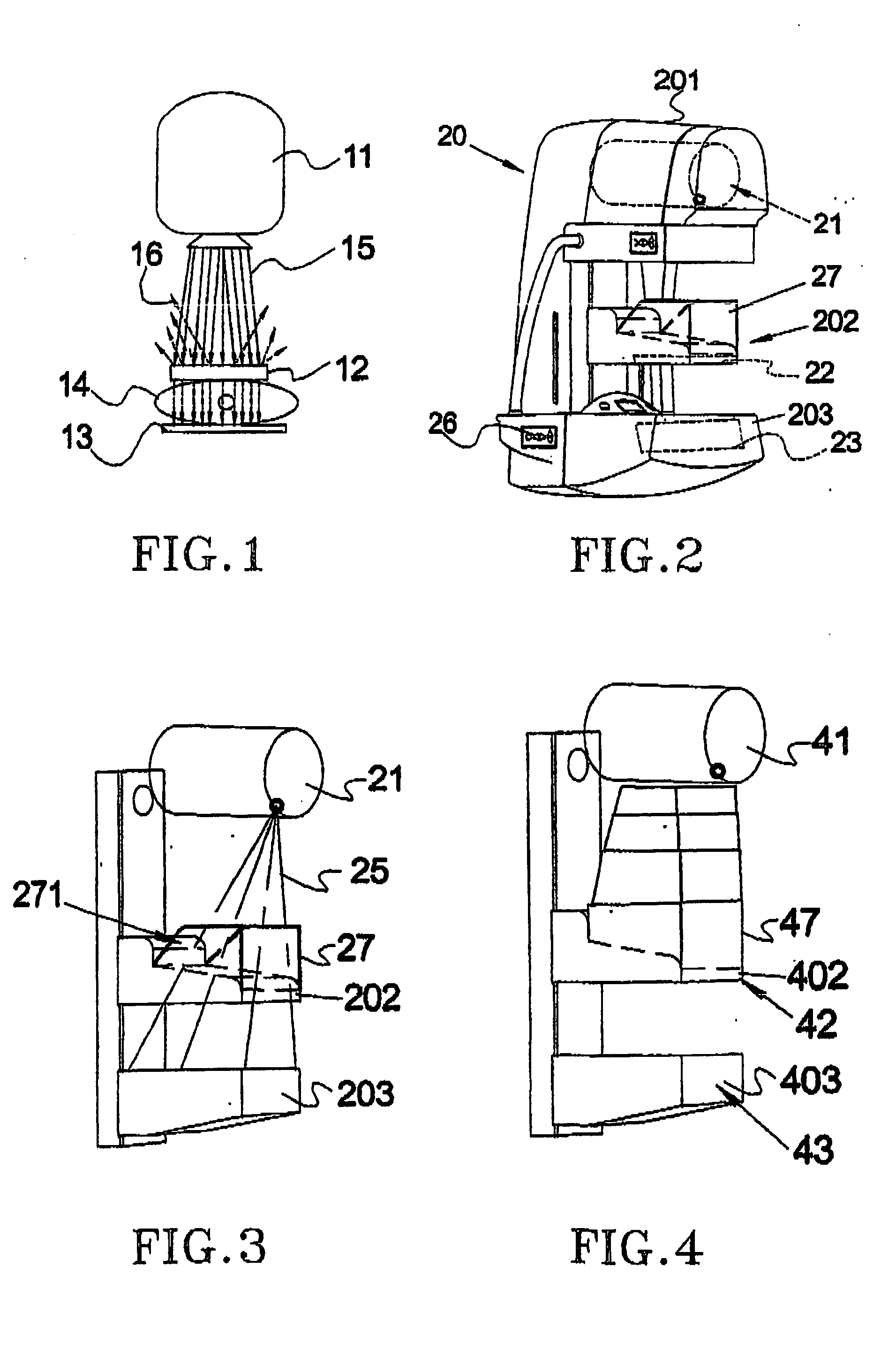
[0030] A second embodiment is schematically illustrated in FIG. 4. This embodiment will be described more closely in relation to FIG. 9 forward. The shielding arrangement 47 is a telescopic frame extending between the x-ray source 41 and the collimator / pedal 42. A detector assembly 43 (not shown) is arranged inside the support 403. Through its telescopic structure, it allows shielding between the entire distance from the x-ray source to the pedal. It is also possible to arrange a curtain shaped shielding, e.g. in shape of accordion folding, made of a flexible material containing x-ray blocking material.

third embodiment

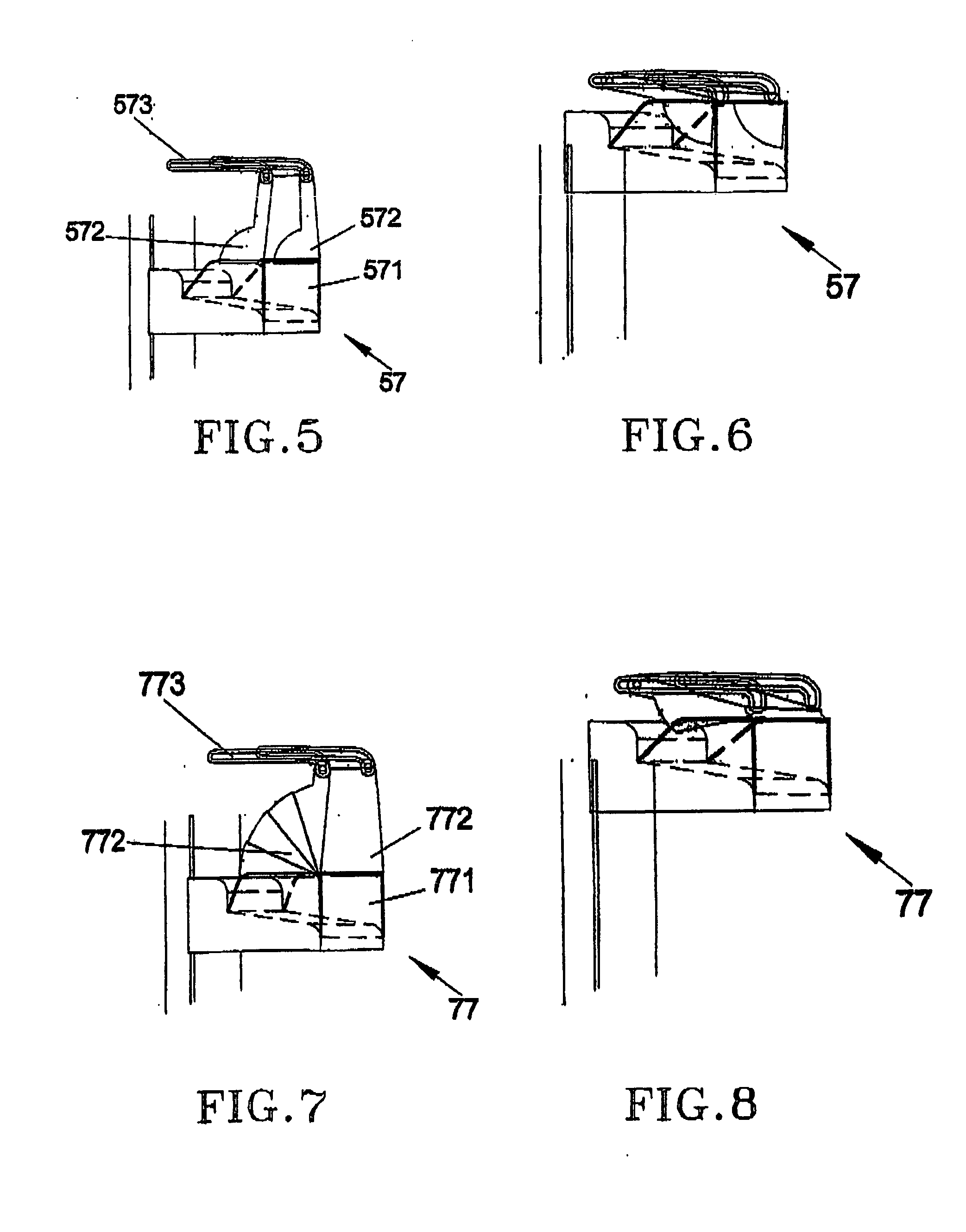
[0031] the invention is illustrated in FIGS. 5 and 6. The shielding arrangement 57 comprises a base portion 571, two substantially L-shaped side portions 572 each connected to an upper part such as the x-ray source housing (not shown) through links 573. The links 573 are provided with grooves in which pegs arranged at the ends of the L-shaped side portions. The side portions are arranged pivoting to the base portion. FIG. 6 shows the shielding arrangement 57 folded when it is in its upper position close to the x-ray source. The lower end of the L-shaped portion, which is substantially circle sector shaped, pivots inside the base portion. This arrangement allows more protection as it blocks more of the scattering beams.

fourth embodiment

[0032] the invention is illustrated in FIGS. 7 and 8. The shielding arrangement 77 is similar to the one according to FIG. 5 and comprises a base portion 771, two sectors of a circle and fan shaped side portions 772 each connected at upper part to the x-ray source housing (not shown) through links 773. The links 773 are provided with grooves in which pegs arranged at the ends of the fan shaped side portions can be moved. The side portions are arranged foldable. FIG. 8 shows side portions of the shielding arrangement 77 folded when it is in its upper position close to the x-ray source.

[0033] The arrangement of FIG. 4 is illustrated in more detail in FIGS. 9 and 10, showing frontal and side views, respectively of the x-ray apparatus 400. Parts of the housing and shield are cut away to illustrate the shield 47 structure. The telescopic shield comprises a number of boxes 471 having different sizes: the one closes to the paddle 403 being the larges and the one closest to the source being...


PUM


Abstract

A shielding arrangement for an x-ray apparatus, preferably for mammography examination is disclosed, and comprises at least an x-ray source, a collimator arrangement and a detector assembly, whereby the collimator is arranged between the x-ray source and the detector assembly and through which x-rays pass. The shielding arrangement, at least partly made of x-ray blocking material and provided for blocking, scattering and/or reflecting x-rays is arranged, at least partly, in a space between the x-ray source and collimator.

Description

TECHNICAL THE OF THE INVENTION [0001] The present invention relates to a shielding arrangement In an x-ray imaging apparatus for mammography, for protecting a patient (person to be examined) and the operator (nurse) against scattered and reflected x-rays. [0002] More specially, the invention relates to x-ray apparatuses, which at least comprise an x-ray source, a collimator arrangement and a detector assembly, whereby said collimator is arranged between said x-ray source and said detector assembly and through which x-rays pass. BACKGROUND OF THE INVENTION [0003] When examining persons by means of x-ray, especially for mammography, the person and the operator are usually exposed to scattered and reflected x-rays. [0004]FIG. 1 is a schematic side view of a digital mammography apparatus 10 comprising a radiation source 11, a collimator 12 and a detector assembly 13. The breast 14, to be examined is pressed to and flattened between the pedals containing the collimator and detector assem...

Claims


Application Information

Patent Timeline
IPC IPC(8): A61B6/00A61B6/10
CPCA61B6/502A61B6/107
Inventor DANIELSSON, MATSHJARN, TORBJORN
Owner PHILIPS DIGITAL MAMMOGRAPHY SWEDEN
Why Eureka
Try Eureka