Epitaxial growth system for fast heating and cooling

a growth system and silicon carbide technology, applied in the direction of crystal growth process, polycrystalline material growth, chemically reactive gas growth, etc., can solve the problems of silicon carbide epitaxy at very high temperatures, difficult to achieve, and insulation generally increases the time necessary to heat up and cool down the system, so as to reduce or eliminate the amount of heat, the effect of quick and efficient heating of the system

Inactive Publication Date: 2013-04-30
PRONOMIC IND
View PDF16 Cites 1 Cited by
  • Summary
  • Abstract
  • Description
  • Claims
  • Application Information

AI Technical Summary

Benefits of technology

[0013]The reflective shield can aid in quick and efficient heating of the system, however, can increase the time necessary to cool the system. Accordingly, in an illustrative embodiment of the invention, the reflective shield can be moved with respect to the heating cylinder into a position where it will reduce or eliminate the amount of heat reflected back to the susceptor apparatus.

Problems solved by technology

Epitaxy at very high temperatures, such as silicon carbide (SiC) epitaxy which is conducted at around 1600° C., is very difficult to accomplish due to the erosion of the hot zone parts of the reactor and thermal losses due to radiation.
The insulation generally increases the time necessary to heat up and cool down the system.
Due to the large distance from the susceptor to the coil and the large amount of insulation, this system is long in heat-up and cool-down time.
Furthermore, the insulation is very thick on the top and bottom of the susceptor which also increases the cool down time.
Finally, the temperature uniformity is not very good in such a configuration and the required power is high.
Both the rigid insulation and to a lesser extent the graphite felt insulation are somewhat conducting, which adds to the heating losses in case of rf heating.
Furthermore, the insulation being fairly thick will increase the distance between the graphite to the coil, which reduces the coupling efficiency.
Due to the thermal insulation and the fact that the susceptor is far away from the coil the heat up and specifically cool down takes a very long time, which dramatically reduces the throughput of the reactor.
This is generally not an acceptable design because of the heat losses and power necessary.
In any of these arrangements the rf heating into the susceptor will cause hot spots due to arcing between the sides and the top and bottom walls.
The arcing will erode the graphite and damage the susceptor.
This, however, can add expense to the reactor design.
The throughput, however, is limited by the heat up, cool down, pump down, and reload times. The heat up can today take about 40 min to 1 hour.

Method used


Image

  • Epitaxial growth system for fast heating and cooling
  • Epitaxial growth system for fast heating and cooling
  • Epitaxial growth system for fast heating and cooling

Examples


Embodiment Construction

[0019]Systems and methods of crystal growth, such as epitaxial growth, are disclosed herein. The disclosed systems and methods may provide faster heating and cooling phases as desired before, during and after crystal growth.

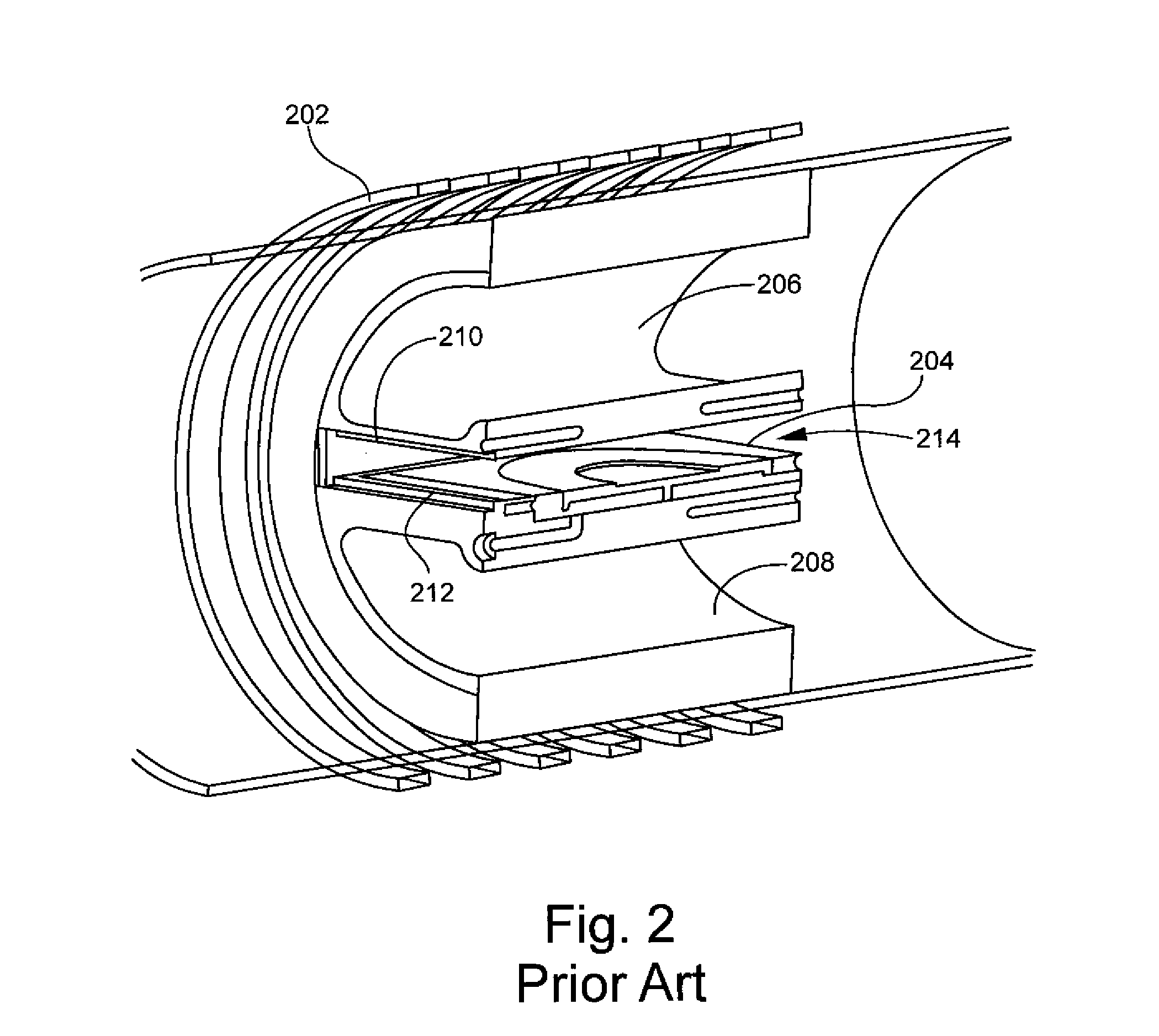
[0020]A susceptor of the type depicted in FIG. 2 is suitable for use in a quick heating and cooling system because it maintains a uniform and reasonably close distance to the coil. Except for the insulation, as shown in FIG. 2, heat-up and cool-down can be made reasonably fast in this configuration. Without any insulation the radiative losses at 1600° C. are prohibitive. Therefore, some type of insulation is needed. In an illustrative embodiment of the invention, a non-conducting reflective shield is placed in a fluid-cooled jacket. Currently, the most practical fluid to use is water. The reflective shield with jacket is disposed between the coil and heating tube.

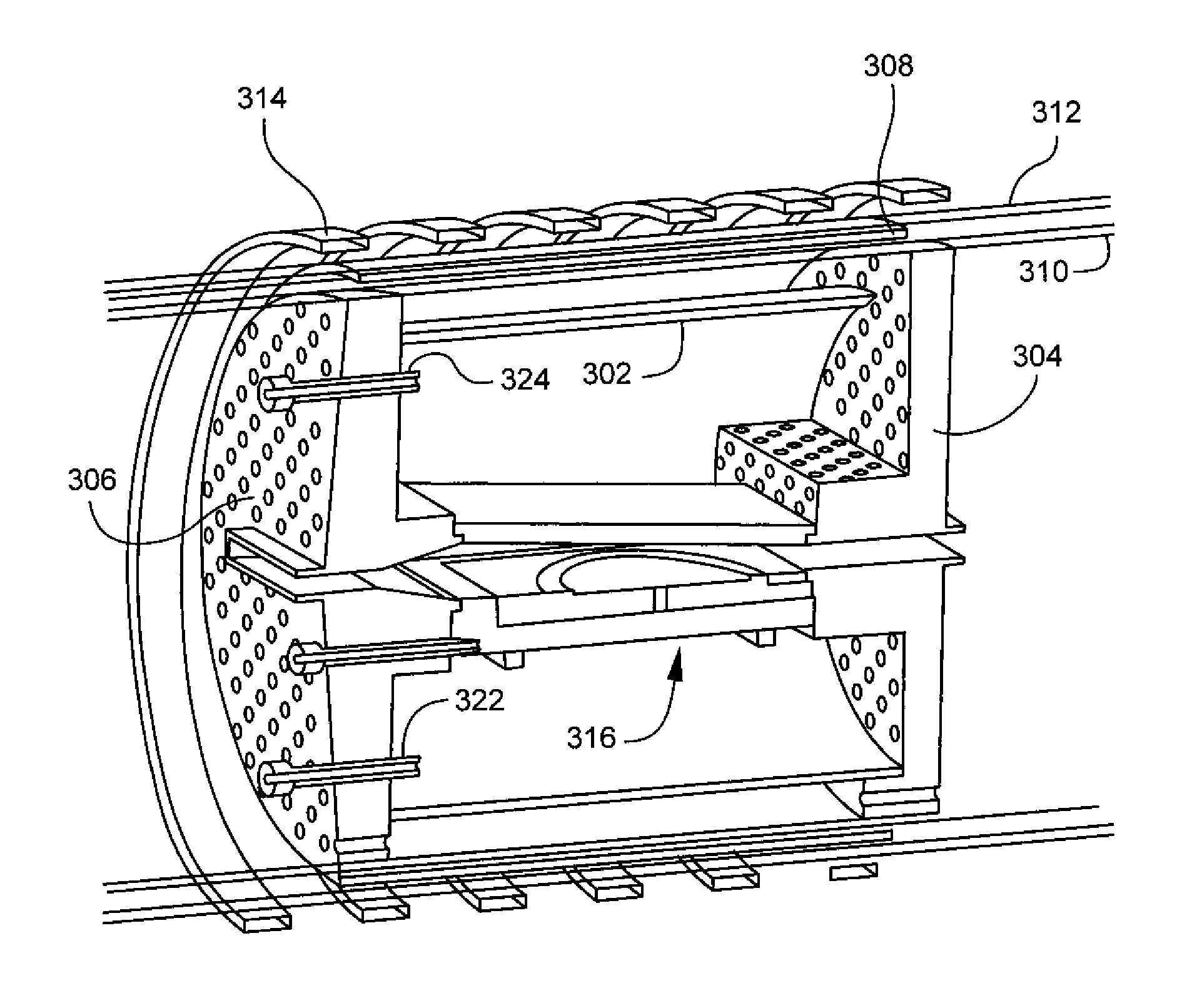
[0021]FIG. 3 depicts a susceptor assembly with a fluid-cooled jacket according to an illustrative emb...


PUM

PropertyMeasurementUnit
temperaturesaaaaaaaaaa
temperatureaaaaaaaaaa
areaaaaaaaaaaa

Abstract

A system for crystal growth having rapid heating and cooling. A fluid-cooling jacket having a reflective shield contained therein is disposed around a heating cylinder in which crystal growth takes place. A heating coil is disposed round the cooling jacket. The invention also includes a method of crystal growth and semiconductor devices formed using the inventive methods and systems.

Description

[0001]This application is based on, and claims priority to, U.S. provisional application, Ser. No. 60 / 901,864, having a filing date of Feb. 16, 2007, entitled Epitaxial Growth System for Fast Heating and Cooling.FIELD OF THE INVENTION[0002]The invention relates a method and apparatus for crystal growth, particularly applicable to epitaxial growth of silicon carbide.BACKGROUND OF THE INVENTION[0003]Epitaxy at very high temperatures, such as silicon carbide (SiC) epitaxy which is conducted at around 1600° C., is very difficult to accomplish due to the erosion of the hot zone parts of the reactor and thermal losses due to radiation. The hot zone materials are usually made from coated graphite surrounded by thick insulation consisting of rigid graphite insulation or graphite felt insulation. The insulation generally increases the time necessary to heat up and cool down the system.[0004]FIG. 1 is a section view of a portion of a prior art reactor showing a rectangular susceptor 102 surro...

Claims


Application Information

Patent Timeline
Patent Type & Authority Patents(United States)
IPC IPC(8): C23C16/00C23C16/46
CPCH01L21/67109
Inventor KORDINA, OLOF CLAES ERIKBERGE, RUNE
Owner PRONOMIC IND
Why Eureka
Try Eureka