Automatic identification method for pouring gate of cast-in-place mold

An automatic identification and pouring gate technology, which is applied in character and pattern recognition, construction, building structure, etc., can solve problems such as labor-intensive, slurry leakage construction errors, and inability to realize real-time monitoring

Inactive Publication Date: 2022-01-18
广东天凛高新科技有限公司
View PDF0 Cites 0 Cited by
  • Summary
  • Abstract
  • Description
  • Claims
  • Application Information

AI Technical Summary

Problems solved by technology

[0002] In the existing building construction technology, the latest construction technology for the inner partition wall is integral cast-in-place molding, the mold and the existing wall surface or ground that can be in contact with the surroundings form a cavity that can be poured with wall slurry, and A pouring port is set on the top of the formwork, and a pouring pipe is inserted into the pouring port to pour the wall slurry into the chamber; the mold and the pulping equipment are generally set separately. The pouring pipe on the mold is inserted into the pouring mouth of the mold or fixed above the pouring mouth. This connection method requires manpower and cannot guarantee the accuracy and firmness of the connection between the pouring pipe and the pouring mouth, resulting in problems caused by substandard manual operations. slurry leakage and other construction errors, and the above scheme is difficult to manage during the implementation process, real-time monitoring cannot be realized, and labor is required

Method used


Image

  • Automatic identification method for pouring gate of cast-in-place mold
  • Automatic identification method for pouring gate of cast-in-place mold
  • Automatic identification method for pouring gate of cast-in-place mold

Examples


Embodiment Construction

[0028] The present invention will be described in further detail below in conjunction with the accompanying drawings and specific embodiments.

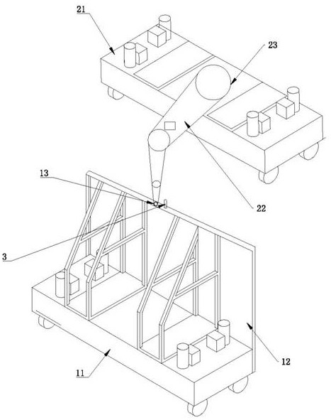
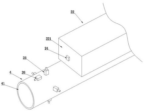
[0029] Such as Figure 1-Figure 4 As shown, a method for automatic identification of the pouring port of a cast-in-place mold includes two relatively set mold devices, a pulping device, and a light source 3. After the two mold devices contact each other, a cavity for accommodating the pouring slurry is formed. The mold device The upper end is provided with a pouring port 13 for pouring slurry; the light source 3 is arranged on the mold device; the slurry making device is located above the pouring port 13, and the cross section of the pouring port 13 is circular.

[0030] The mold device includes a mold body 11 and a formwork 12 for pouring and molding. The formwork 12 is arranged on one side of the mold body 11, the pouring port 13 is arranged on the top surface of the formwork 12, and the light source 3 is arranged on the top surface...


PUM


Abstract

The invention provides an automatic identification method for a pouring gate of a cast-in-place mold. Two mold devices, a slurrying device and a light source are included. The slurrying device is located above the pouring gate, and the cross section of the pouring gate is circular; The method comprises the following steps: the slurrying device is moved to the side of one mold device; an image recognition module accurately finds a pouring gate through an image recognition algorithm; a mechanical arm adjusts the orientation of the end of the mechanical arm according to the recognized relative position relation between the pouring gate and the datum point of the image recognition device; the mechanical arm moves towards the identified position of the pouring gate, a distance measuring module at the end of the mechanical arm feeds back the distance between the mechanical arm and the pouring gate in real time, and the mechanical arm moves towards the pouring gate; in the moving process of the mechanical arm, the position of the mechanical arm is adjusted according to an obstacle avoidance module; when the distance measuring module recognizes that the position of the template is smaller than the distance between the pouring pipe and the distance measuring module, it is judged that the pouring pipe is inserted into the pouring gate; and the pouring pipe and the pouring gate in the mold can be automatically inserted and connected.

Description

technical field [0001] The invention relates to the technical field of cast-in-place buildings, in particular to an automatic identification method for pouring openings of cast-in-place molds. Background technique [0002] In the existing building construction technology, the latest construction technology for the inner partition wall is integral cast-in-place molding, the mold and the existing wall surface or ground that can be in contact with the surroundings form a cavity that can be poured with wall slurry, and A pouring port is set on the top of the formwork, and a pouring pipe is inserted into the pouring port to pour the wall slurry into the chamber; the mold and the pulping equipment are generally set separately. The pouring pipe on the mold is inserted into the pouring mouth of the mold or fixed above the pouring mouth. This connection method requires manpower and cannot guarantee the accuracy and firmness of the connection between the pouring pipe and the pouring m...

Claims


Application Information

Patent Timeline
Patent Type & Authority Applications(China)
IPC IPC(8): G06V20/00G06V10/44E04G21/02E04G21/04
CPCE04G21/0436E04G21/025
Inventor 邓家辉于尧臣
Owner 广东天凛高新科技有限公司
Why Eureka
Try Eureka