
Pixel circuit and driving method thereof

A pixel circuit and drive transistor technology, applied in instruments, static indicators, etc., can solve the problems of different luminance of light-emitting devices and affect the display effect, etc., and achieve the effect of improving the overall display effect, improving visual effects, and consistent luminous intensity

Active Publication Date: 2022-01-18
BLACK COW FOOD
View PDF10 Cites 0 Cited by
  • Summary
  • Abstract
  • Description
  • Claims
  • Application Information

AI Technical Summary

Problems solved by technology

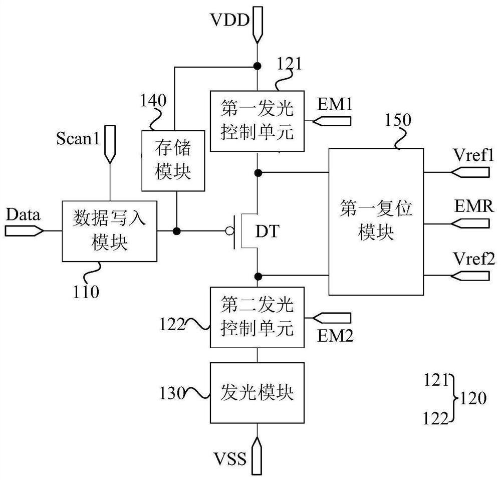
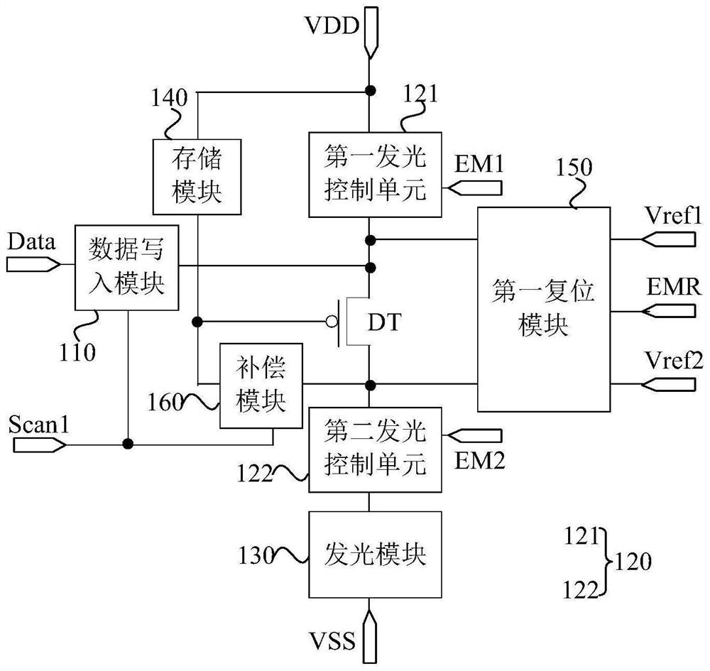
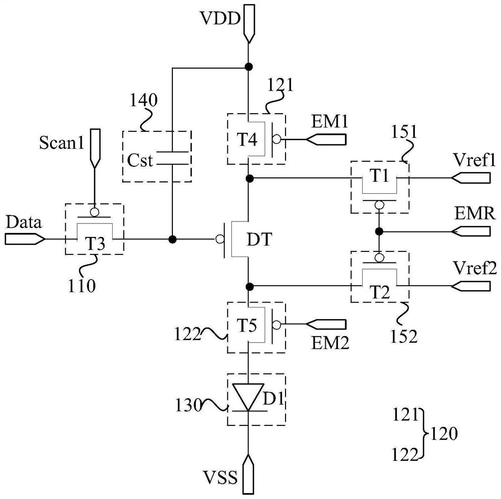
[0004]However, under different effective level pulses of the light emission control signal, the source node potential of the driving transistor in the pixel circuit will be different, and the drain of the driving transistor in the pixel circuit will The potential of the nodes will also be different, resulting in different luminous brightness of the light-emitting device under different effective level pulses of the light-emitting control signal in each frame, which affects the display effect

Method used


Image

  • Pixel circuit and driving method thereof
  • Pixel circuit and driving method thereof
  • Pixel circuit and driving method thereof

Examples


Embodiment Construction

[0044] The present invention will be further described in detail below in conjunction with the accompanying drawings and embodiments. It should be understood that the specific embodiments described here are only used to explain the present invention, but not to limit the present invention. In addition, it should be noted that, for the convenience of description, only some structures related to the present invention are shown in the drawings but not all structures.

[0045]As mentioned in the background art, under different effective level pulses of the light emission control signal, the potential of the source node of the driving transistor in the pixel circuit will be different, and the potential of the drain node of the driving transistor in the pixel circuit will also be different, resulting in that each frame The light-emitting brightness of the light-emitting device is different under different effective level pulses of the internal light-emitting control signal, which af...


PUM


Abstract

The invention discloses a pixel circuit and a driving method thereof. A first reset module writes a first reset voltage into a first electrode of a driving transistor and writes a second reset voltage into a second electrode of the driving transistor in a reset sub-stage of a light-emitting stage, so that in each reset sub-stage in the light-emitting stage, the potential of the first electrode of the driving transistor is reset to a first reset voltage, and the potential of the second electrode of the driving transistor is reset to a second reset voltage, so that the potential of the first electrode of the driving transistor is equal, the potential of the second electrode of the driving transistor is equal after each reset sub-stage and before the light-emitting sub-stage; therefore, the influence degrees of the first electrode potential and the second electrode potential of the driving transistor on the driving current generated by the driving transistor in different light-emitting sub-stages are consistent, the light-emitting intensity of the light-emitting module is consistent, the light-emitting brightness difference of the light-emitting module in different light-emitting sub-stages is reduced, and the visual effect is improved.

Description

technical field [0001] Embodiments of the present invention relate to the field of display technology, and in particular to a pixel circuit and a driving method thereof. Background technique [0002] With the development of display technology, people have higher and higher requirements for display effects. [0003] In the pixel circuit of the prior art, it usually includes a driving transistor and a light-emitting control module for controlling the light-emitting device. In one frame, the light-emitting device is improved by providing a light-emitting control signal including a plurality of active level pulses to the light-emitting control module. The luminous frequency, thereby enhancing the visual effect of the human eye. [0004] However, under different effective level pulses of the light-emitting control signal, the potentials of the source node of the driving transistor in the pixel circuit will be different, and the potentials of the drain node of the driving transis...

Claims


Application Information

Patent Timeline
Patent Type & Authority Applications(China)
IPC IPC(8): G09G3/32G09G3/3233
CPCG09G3/32G09G3/3233G09G2320/0233
Inventor 朱正勇赵欣孙光远贾溪洋
Owner BLACK COW FOOD
Learn More