
Encoding method for batching counter

A counter and digital coding technology, which is applied in the field of counter coding, can solve the problems of inability to accurately distinguish critical carry positions, inability to detect sensor faults in time, and different luminous intensities of emission tubes, etc., and achieve simple structure, consistent luminous intensity, and easy production Effect

Active Publication Date: 2013-08-14
CHENGDU QIANJIA TECH CO LTD
View PDF1 Cites 0 Cited by
  • Summary
  • Abstract
  • Description
  • Claims
  • Application Information

AI Technical Summary

Problems solved by technology

Invention patent 200810067429.7 discloses a coding method of a counter coding character wheel. The circumferential surface of the counter coding character wheel is divided into ten numbers from "0" to "9" for manual reading at an angle of 36°. The end face of the code wheel is designed with three fan-shaped light-transmitting hole slots that are concentric with the center of the character wheel and on the same circumferential line to complete the coding. °Five pairs of photoelectric sensors with evenly distributed angles generate thirty different sets of 5-digit binary coded electrical signals in turn, corresponding to the ten numbers "0~9" on the code wheel of the counter, and each number corresponds to three groups of 5-digit binary codes Digital coding, this coding method produces a large number of codes, and when the photoelectric sensor fails, reading errors are prone to occur, and sensor faults cannot be found in time; this coding requires high mold precision, and cannot accurately distinguish the critical carry position during linkage carry , resulting in coding errors and reading errors at the time of critical carry, and complex software algorithms are required to correct the carry problem; the angle between the sensors is only 36°, resulting in a relatively close distance between two adjacent sensors, and only time-sharing sampling during sampling, which limits the emission The driving method of the tube can only be parallel constant voltage mode, and the emission tube driven by parallel constant voltage is very easy to cause the inconsistency of the driving current due to the inconsistency of the voltage drop of the emission tube, which will lead to the difference in the luminous intensity of the emission tube, which will affect the reading accuracy and cause wrong reading

Method used


Image

  • Encoding method for batching counter
  • Encoding method for batching counter
  • Encoding method for batching counter

Examples


Embodiment 1

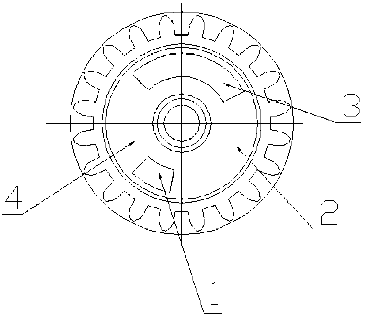
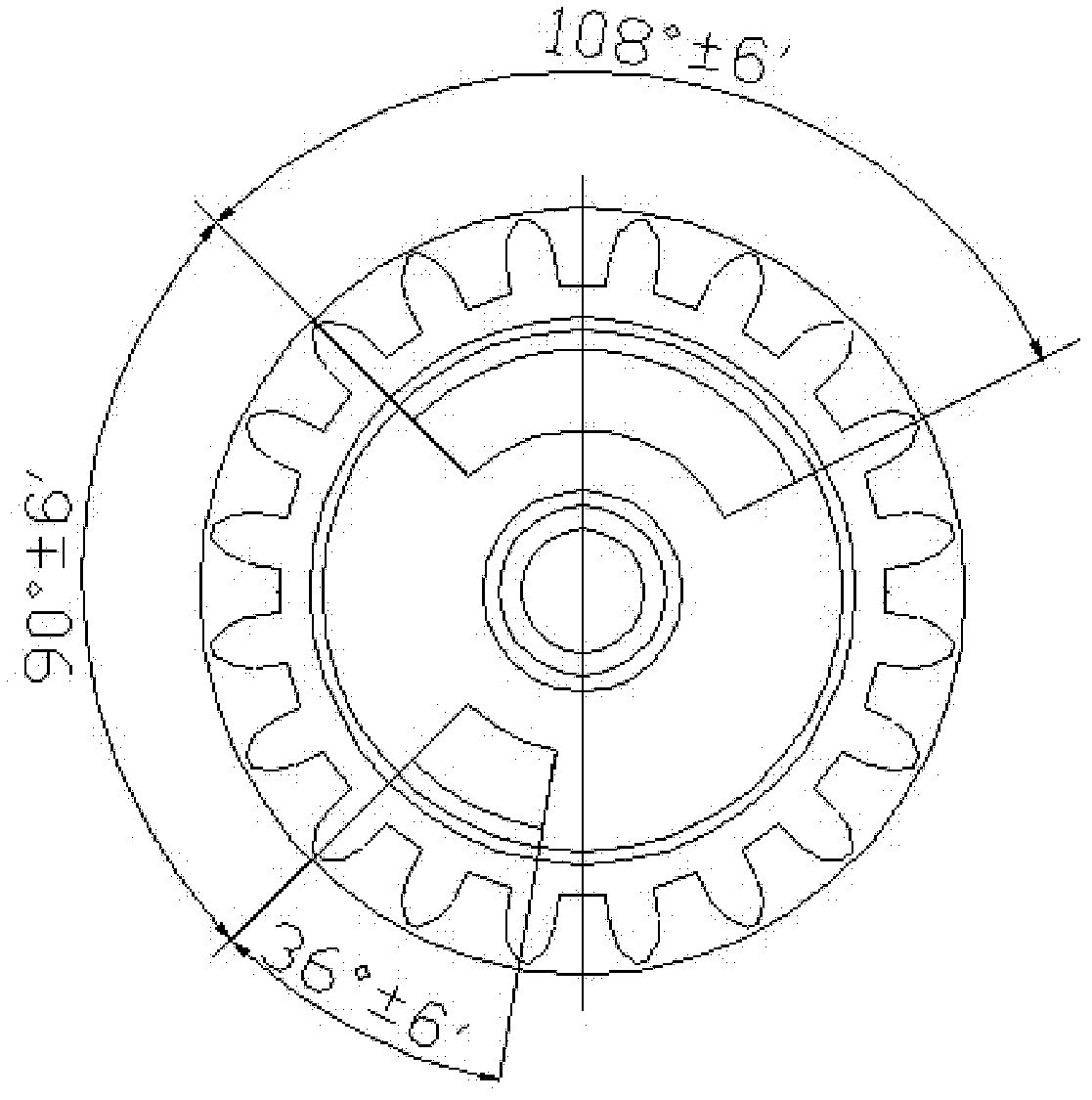
[0048] exist image 3 Among them, the arc angle of the translucent zone (1) α is 36°, the arc angle β of the opaque zone (2) is 126°, and the arc angle of the translucent zone (3) is 0 The value is 108°, and the arc angle ε of the opaque zone (4) is 90°.

Embodiment 2

[0050] exist image 3 Among them, the angle α of the arc of the first translucent zone (1) is 36°+6′, the angle β of the arc of the first opaque zone (2) is 126°+6′, and the value of the arc angle β of the second translucent zone The arc angle θ of the light band (3) is 108°-6', and the arc angle ε of the second opaque band (4) is 90°-6'.

Embodiment 3

[0052] exist image 3 Among them, the angle α of the arc of the first light-transmitting zone (1) is 36°-6′, the angle β of the arc of the first opaque zone (2) is 126°-6′, and the value of the angle β of the arc of the second translucent zone The arc angle θ of the light band (3) is 108°+6', and the arc angle ε of the second opaque band (4) is 90°+6'.


PUM


Abstract

The invention relates to an encoding method of a counter and in particular relates to an encoding method for a batching counter. The encoding method for the batching counter comprises the following steps of: sequentially manufacturing 360-deree circumference of the side surface of a character wheel into a first light-permeable strip, a first light-impermeable strip, a second light-permeable stripand a second light-impermeable strip, wherein the arc included angle of the first light-permeable strip is alpha, the arc included angle of the first light-impermeable strip is beta, the arc includedangle of the second light-permeable strip is theta and the arc included angle of the second light-impermeable strip is epsilon; and rotating a circle of the character wheel of the batching counter, sequentially generating twenty groups of different 5-bit binary numeric coding electric signals by a photoelectric sensor consisting of five pairs of light emitting tubes and photosensitive receiving tubes arranged at two sides of an encoding character wheel so as to correspond to ten numbers namely '0'-'9' on the character wheel of the batching counter, wherein each number corresponds to two groups of 5-bit binary codes. According to the encoding method for the batching counter in the invention, the encoding precision can be improved and the cost can be lowered.

Description

technical field [0001] The invention relates to a method for coding a counter, in particular to a method for coding a metering counter. Background technique [0002] Remote transmission direct-reading water meters, gas meters, electric meters, etc. need to encode the display numbers corresponding to the rotation position of the counter coding wheel to output the electrical signal to the measuring instruments and meters. At this time, the coding method for the counter coding wheel of the meter is particularly important important. Invention patent 200810067429.7 discloses a coding method of a counter coding character wheel. The circumferential surface of the counter coding character wheel is divided into ten numbers from "0" to "9" for manual reading at an angle of 36°. The end face of the code wheel is designed with three fan-shaped light-transmitting hole slots that are concentric with the center of the character wheel and on the same circumferential line to complete the co...

Claims


Application Information

Patent Timeline
Patent Type & Authority Patents(China)
IPC IPC(8): G06K7/10
Inventor 赵勇雷新民谢木军胡芸华刘新权何菲
Owner CHENGDU QIANJIA TECH CO LTD
Learn More