Motor and magnetic brake

A magnetic brake and magnetic brake technology, applied in the direction of motors, electric vehicles, electrical components, etc., can solve the problems of inability to complete automatic parking, poor applicability of in-wheel motors, etc., to facilitate motor assembly, eliminate accumulated errors, and meet parking requirements. The effect of the hill brake function

Pending Publication Date: 2022-01-18
NANJING KANGNI SMART TECH CO LTD
View PDF1 Cites 0 Cited by
  • Summary
  • Abstract
  • Description
  • Claims
  • Application Information

AI Technical Summary

Problems solved by technology

But there is no feasible solution in the form of dual drive function
[0003] Moreover, since the existing hub motors generally do not have a power-off automatic braking function, in the case of a normal uphill and downhill power failure, automatic parking cannot be completed, and manual control is required to complete the braking.
In some mobile equipment with higher special safety requirements, such as electric wheelchairs, AGV vehicles, etc., the applicability of such in-wheel motors is poor

Method used


Image

  • Motor and magnetic brake
  • Motor and magnetic brake
  • Motor and magnetic brake

Examples


Embodiment

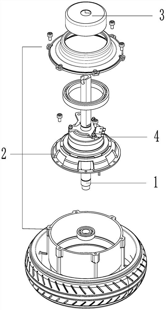
[0031] The motor of this embodiment is as figure 1 As shown, it is composed of a stator assembly 1, a rotor assembly 2 and a magnetic brake 4, and a magnetic brake protective cover 3 for waterproof and dustproof is installed on the magnetic brake 4.

[0032] In the stator assembly 1, the stator punches are stacked and wound to assemble the electric appliance, and then connected to the motor shaft through a flat key. The magnetic steel sheet is attached to the inner side of the rotor, and the other side of the rotor is screwed to the gear train components, connected through the sun gear, planetary gear, ring gear and hub, to reduce the output of the motor and increase the torque.

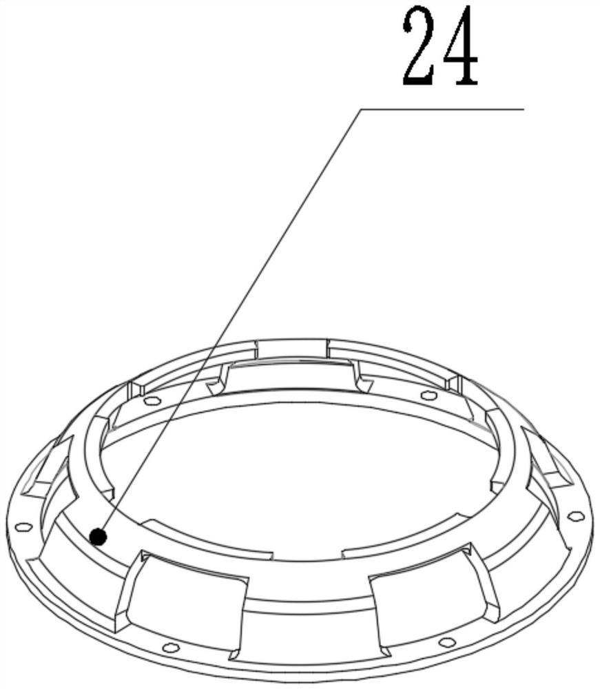
[0033] In the rotor assembly 2 , the rotor opening side is screwed and fixed to the rotor cover 24 , and the rotor assembly is used to convert electrical energy into kinetic energy. Such as figure 2 The rotor cover 24 shown has a slot matching the ear on the outer circumference of the friction pla...


PUM


Abstract

The invention provides a motor and a magnetic brake, and the motor comprises a stator assembly, a rotor assembly and the magnetic brake; the magnetic brake comprises a magnetic brake seat, a moving plate, a friction plate and a fixed plate, wherein the moving plate can axially move relative to the magnetic brake seat, and the fixed plate is fixedly connected with the magnetic brake seat; the magnetic brake is electrified to release braking during power-on, and the magnetic brake loses power to brake during power-off. A full-ring friction plate structure which is in movable contact with the rotor cover is adopted, so the process control of motor assembly is facilitated, and poor products caused by axial accumulated errors can be eliminated; moreover, the double-sided brake contact area is larger, and the brake effect is stronger.

Description

technical field [0001] The invention relates to a motor, in particular to a hub motor and an electromagnetic braking device for the motor. Background technique [0002] The hub motors of existing electric vehicles use brushless toothless or brushless toothed motors, and these two types are widely used in various products at present. Its braking is accomplished by relying on external mechanical structures or electronic brakes. The structure of the mechanical brake is complicated, and dust and sand will enter the exposed part of the brake, which will weaken the braking effect. The wiring of the brake cable and the brake handle will occupy the space of the whole vehicle, affecting the appearance of the whole vehicle, and the overall cost is high; the effect of the electronic brake is poor at low speeds. , no parking brake capability. At the same time, there are currently some solutions for the single drive function of the hub motor on the market. But there is no feasible sol...

Claims


Application Information

Patent Timeline
Patent Type & Authority Applications(China)
IPC IPC(8): H02K7/102
CPCH02K7/1021H02K7/102Y02T10/64
Inventor 唐达联张墨染蔡超
Owner NANJING KANGNI SMART TECH CO LTD
Why Eureka
Try Eureka