
Hoisting equipment for fabricated building construction

A technology of building construction and hoisting equipment, which is applied in the direction of construction, building structure, and building material processing, etc. It can solve the problems of building damage, high work intensity, and easy swing of hanging ropes, etc., and achieve the effect of ensuring effective use

Pending Publication Date: 2022-01-21
CHINA 22MCC GROUP CORP
View PDF0 Cites 0 Cited by
  • Summary
  • Abstract
  • Description
  • Claims
  • Application Information

AI Technical Summary

Problems solved by technology

[0002] Buildings assembled from prefabricated parts and components on site are called prefabricated buildings. According to the form and construction method of prefabricated components, they can be divided into five types: block building, plate building, box building, skeleton plate building and rising plate building. One type, the prefabricated building needs to use hoisting equipment during the construction process. The conventional hoisting equipment is to use the crane to cooperate with the hook for construction. In the specific construction process of such hoisting equipment, when the assembly component angle is not suitable for hoisting, Staff are required to assist in steering, which is not only intensive, but also dangerous. Conventional slings tend to swing during rotation. When hoisting at a high place, the operation is more difficult, and it is easy to cause the problem of the hoisting angle. In the case of damage to the building, for this reason, a hoisting device for prefabricated building construction is proposed, which can automatically adjust the angle and effectively ensure the quality of the building

Method used

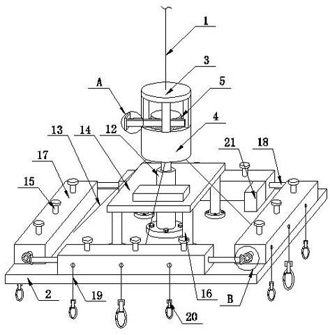
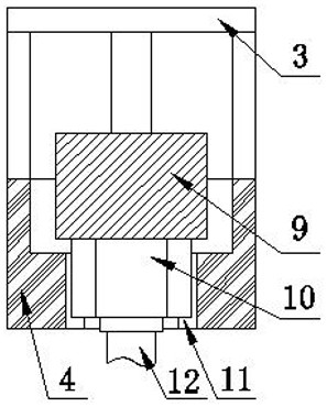
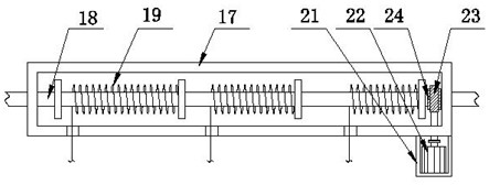

Image

  • Hoisting equipment for fabricated building construction
  • Hoisting equipment for fabricated building construction
  • Hoisting equipment for fabricated building construction

Examples


Embodiment Construction

[0021] The present invention will be further described below in conjunction with the embodiments, the purpose is only to better understand the content of the present invention, therefore, the examples do not limit the protection scope of the present invention.

[0022] see Figure 1-Figure 5 , a prefabricated building construction hoisting equipment, including hoisting rope 1, hoisting plate 2, transfer cover 3, step bucket 4, step column 5, adjusting telescopic rod 6, push plate 7, tooth plate 8, gear column 9, Spline column 10, spline groove 11, lift telescopic rod 12, reinforcement rope 13, reinforcement plate 14, limit winding column 15, reinforcement column 16, storage box 17, linkage rod 18, pull rope 19, pull hook 20, expansion cover 21 , servo motor 22, worm 23, worm gear 24, bevel gear 25, the bottom of the hoisting rope 1 is provided with a transfer cover 3, the bottom of the transfer cover 3 is connected with the ladder bucket 4 through connecting rods, and the ladd...


PUM


Abstract

The invention relates to the technical field of building construction, in particular to hoisting equipment for fabricated building construction. A transfer cover is arranged at the bottom of a hoisting rope, the periphery of the bottom of the transfer cover is connected with a stepped hoisting bucket through a connecting rod, a stepped column is slidably connected with the interior of the stepped hoisting bucket and comprises a gear column and a spline column fixed to the lower portion of the gear column, a tooth plate engaged with the gear column is arranged on the outer surface of the gear column, a push plate is arranged at the end, away from the gear column, of the tooth plate, an adjusting telescopic rod is arranged between the push plate and the connecting rod, a spline groove matched with the spline column is formed in the stepped hoisting bucket, a lifting telescopic rod is fixed to the center of the top of a hoisting plate, the top end of the lifting telescopic rod is rotationally connected with the bottom of the spline column through a bearing, and four reinforcing ropes are arranged between the bottom end of the spline column and the hoisting plate at equal distances. According to the hoisting equipment, automatic steering of assembling components can be realized, and great convenience is provided for hoisting work.

Description

technical field [0001] The invention relates to the technical field of building construction, in particular to a hoisting device for prefabricated building construction. Background technique [0002] Buildings assembled from prefabricated parts at the construction site are called prefabricated buildings. According to the form and construction method of prefabricated components, they are divided into five types: block buildings, plate buildings, box buildings, skeleton plate buildings, and lift-up buildings. This type of hoisting equipment needs to use hoisting equipment during the construction process. The conventional hoisting equipment is to use the crane to cooperate with the hook for construction. In the specific construction process, when the angle of the assembly components is not suitable for hoisting, It requires staff to perform auxiliary steering, which not only has high work intensity, but also has certain dangers. Conventional slings are prone to swing during the...

Claims


Application Information

Patent Timeline
IPC IPC(8): B66C1/14B66C13/08E04G21/16
CPCB66C1/14B66C13/08E04G21/162
Inventor 杨毛毛周晓丽
Owner CHINA 22MCC GROUP CORP
Learn More