
Optical fiber displacement detection system and method with double differential structure

A technology of displacement detection and differential structure, which is applied in the field of displacement sensors, can solve the problem of low sensitivity of low-frequency displacement detection, and achieve the effect of increasing detection sensitivity and improving accuracy

Active Publication Date: 2022-07-19
HUAZHONG UNIV OF SCI & TECH
View PDF7 Cites 0 Cited by
  • Summary
  • Abstract
  • Description
  • Claims
  • Application Information

AI Technical Summary

Problems solved by technology

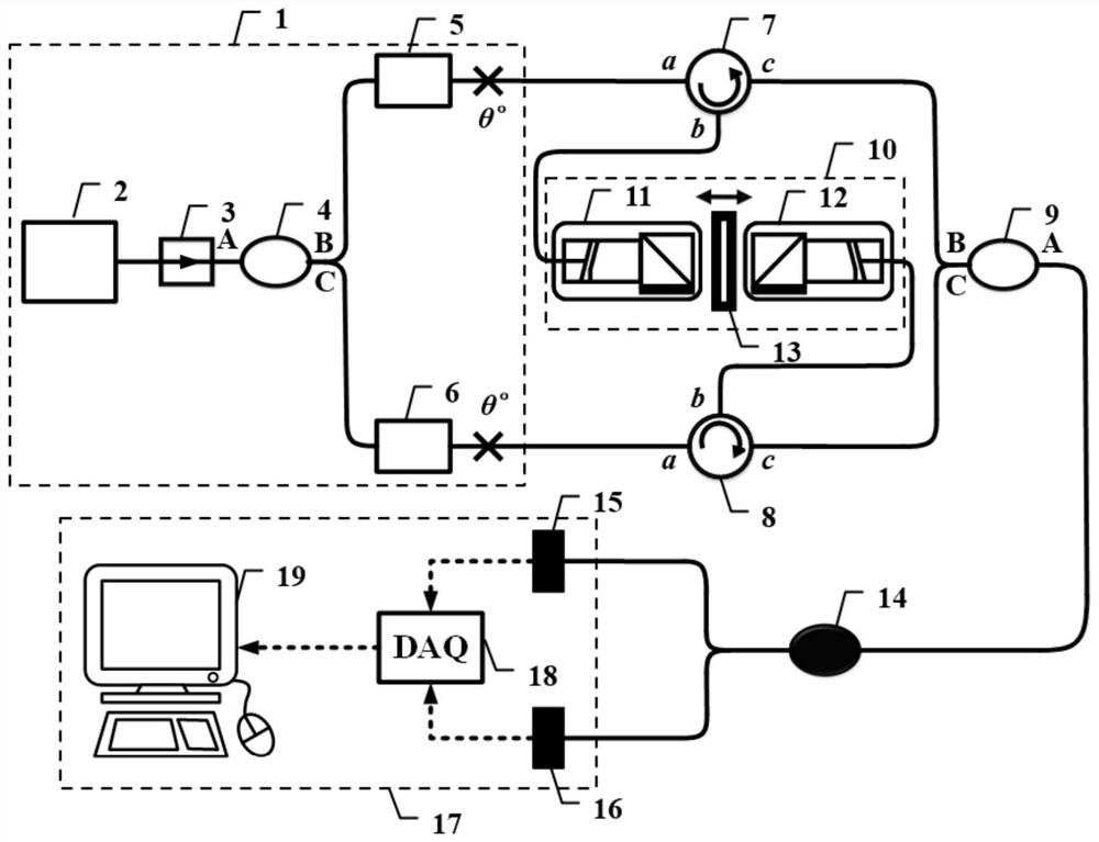
[0005] Aiming at the defects of the prior art, the object of the present invention is to provide an optical fiber displacement detection system and method with a double differential structure, aiming at solving the problem of low sensitivity of low-frequency displacement detection in the existing optical fiber displacement detection system

Method used


Image

  • Optical fiber displacement detection system and method with double differential structure
  • Optical fiber displacement detection system and method with double differential structure
  • Optical fiber displacement detection system and method with double differential structure

Examples


Embodiment

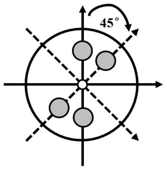
[0111] The output light frequency of the narrow linewidth fiber laser is 193.5THz (the corresponding light wavelength is 1550nm); the θ° fusion is 45°, such as image 3 Shown is a schematic diagram of the cross-section of two optical fibers spliced ​​at 45° in the embodiment. By splicing at 45°, the single-polarized light in one optical fiber can be divided into two beams of orthogonally polarized light with a power of 1:1; The frequency shift amount is 80.01MHz, the frequency shift amount of the second frequency shifter is 80MHz, and the frequency shift difference Δf of the two interference lights transmitted from the isolator is 10kHz; the first space value is 3mm at the initial moment, the second space The value is 2mm at the initial moment; the frequency f 1 The length of the optical fiber that the light passes through 1 is 10.001m, frequency f 2 The length of the optical fiber that the light passes through 2 is 10m, the slow-axis refractive index n of the polarization-...


PUM


Abstract

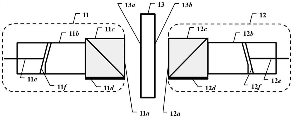
The invention provides an optical fiber displacement detection system and method with a double differential structure, belonging to the field of displacement sensors. to the first end face of the object to be tested; the second collimating beam splitter reflects the second fast-axis polarized light and transmits the second slow-axis polarized light to the second end face of the object to be tested; the second coupler is used to pass through the object to be tested The slow-axis polarized light reflected by the first end face and the slow-axis polarized light reflected by the second end face of the object to be tested undergo slow-axis interference; and the reflected first fast-axis polarized light and the reflected second fast-axis polarized light produce fast axis interference; the data processor makes a difference between the digital slow-axis interference phase and the fast-axis interference phase, and obtains the displacement change of the object to be measured through the change of the phase difference; the invention is suitable for high-sensitivity displacement sensing in low frequency bands, and broadens the basis of Applicable frequency bands for fiber optic displacement sensors.

Description

technical field [0001] The invention belongs to the field of displacement sensors, and more particularly, relates to an optical fiber displacement detection system and method with a double differential structure. Background technique [0002] Displacement is one of the most basic physical quantities. It is easy to detect and has relatively high detection accuracy. It is often used in scientific research and engineering applications to measure parameters such as acceleration, velocity, pressure, sound waves, and gravitational waves. Common displacement sensing detection methods include capacitive, inductive, magnetoresistive and optical. Among them, the optical fiber displacement sensor has the advantages of light weight, easy installation and connection, and anti-electromagnetic interference. The passive probe is used to avoid the electromagnetic interference of the active device on the inspection object. At the same time, the passive sensor probe is completely separated fr...

Claims


Application Information

Patent Timeline
Patent Type & Authority Patents(China)
IPC IPC(8): G01D5/353G01B11/02
CPCG01D5/35306G01B11/02
Inventor 徐志林石易梁浴榕周泽兵
Owner HUAZHONG UNIV OF SCI & TECH
Learn More