Novel door plate locking device and locking method

A locking device and door panel technology, which is applied in the field of medium and high voltage switchgear, can solve problems such as easy arc spraying on the upper and lower sides, hidden dangers to the personal safety of operation and maintenance and maintenance personnel, and inability to lock the door panel.

Pending Publication Date: 2022-01-25
SHANDONG TAIKAI COMPLETE ELECTRIC APPLIANCE +1
View PDF7 Cites 0 Cited by
  • Summary
  • Abstract
  • Description
  • Claims
  • Application Information

AI Technical Summary

Problems solved by technology

[0003] The above-mentioned technical solution has the following disadvantages: 1. This conventional structure cannot effectively lock the upper and lower sides of the door panel. Once an arcing fault occurs in the cabinet, the upper and lower sides will be weak points prone to arcing, and the strong arcing airflow will make The cabinet door is impacted and deformed, and arcs are ejected from the upper and lower sides, which brings great personal safety hazards to operation, maintenance and repair personnel

Method used


Image

  • Novel door plate locking device and locking method
  • Novel door plate locking device and locking method
  • Novel door plate locking device and locking method

Examples


Embodiment 1

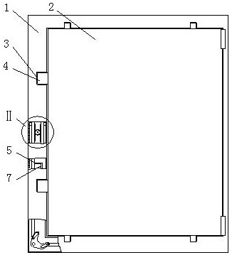
[0026] A novel door panel locking device and locking method, such as Figure 1-2 and Figure 7 shown. It includes a door frame 1 and an inner door 2 hinged on the right side of the door frame 1. The left side, the upper side and the lower side of the door frame 1 are inlaid with a 匚-shaped plate 3 communicating with the inner ring of the door frame 1, and the 匚-shaped plate 3 is provided with Offer the plugboard 4 of jack, described plugboard 4 is fixedly connected on the inner door 2.

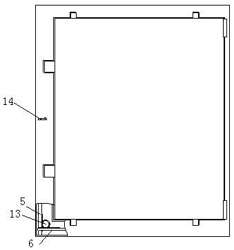
[0027] The left side of the door frame 1 is provided with a drive gear 8 that rotates synchronously with the rotary handle 14, and the two sides of the drive gear 8 are vertically provided with racks 9 meshing with the drive gear 8, and the racks 9 are fixedly connected with the corresponding vertical rods 5 respectively. , the vertical rods 5 are vertically slidably connected to the door frame 1. Both the upper side and the lower side of the door frame 1 are horizontally slidably connected...

Embodiment 2

[0034] Example 2, such as Figure 3-4 shown.

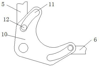
[0035] Compared with Embodiment 1, the difference is that the steering mechanism includes an upper gear 13 and a lower gear 15 fixedly connected coaxially, teeth are provided on the cross bar 6, and the cross bar 6 meshes with the upper gear 13, and the vertical bar 5 and the upper gear 13 mesh. The lower gear 15 meshes, the lower vertical bar 5 is located on the left side of the lower lower gear 15, the upper vertical bar 5 is located on the right side of the upper lower gear 15, and the lower horizontal bar 6 and the upper horizontal bar 6 are located on the lower side of the corresponding upper gear 13.

[0036] The downward movement of the lower vertical rod 5 drives the lower lower gear 15 to rotate counterclockwise, which in turn drives the upper gear 13 to rotate counterclockwise, and the counterclockwise rotation of the upper gear 13 drives the lower horizontal rod 6 to move to the right. Similarly, the upper vertical rod ...

Embodiment 3

[0038] Example 3, such as Figure 4-5 shown.

[0039]Compared with Embodiment 1 and Embodiment 2, the difference is that the steering mechanism includes spherical protrusions 16 fixedly connected to the opposite ends of the two vertical bars 5, and the spherical protrusions 16 face the corresponding cross bars 6, and are fixedly connected to the One end of the L-shaped inserting rod 7 on the cross bar 6 is fixedly connected to the spring 17, and the other end of the spring 17 is fixedly connected to the corresponding 匚-shaped plate 3.

[0040] The downward movement of the lower vertical bar 5 (the upward movement of the upper vertical bar 5) drives the protrusions to move together, and then the protrusions approach the corresponding horizontal bar 6 and press the horizontal bar 6 to move to the right, so that the L-shaped insertion rod 7 Insert it into the corresponding jack. Wherein, when the L-shaped inserting rod 7 is moved out of the jack, the lower vertical bar 5 moves ...


PUM


Abstract

The invention relates to the technical field of middle-high voltage switch cabinets, in particular to a novel door plate locking device and a locking method. The novel door plate locking device comprises a door frame and an inner door, wherein left square bracket-shaped plates are inlaid in the left side, the upper side and the lower side of the door frame, inserting plates with inserting holes are arranged in the left square bracket-shaped plates, and the inserting plates are fixedly connected to the inner door; vertical rods synchronously moving in opposite directions are arranged at the left side of the door frame, the outer ends of the vertical rods are connected with transverse rods through steering mechanisms, the transverse rods and the vertical rods move synchronously, the transverse rods and the vertical rods move transversely, the vertical rods and the transverse rods are located at the outer sides of the corresponding inserting plates, the extending directions of the inserting holes are parallel to the corresponding vertical rods and the transverse rods, and L-shaped inserting rods are arranged at one sides of the vertical rods and the transverse rods; and the inner ends of the inserting rods penetrate through the left square bracket-shaped plates and are opposite to the inserting holes. According to the novel door plate locking device and the locking method, a rotating handle can be rotated to drive a driving gear to rotate, so that the door frame and the left side, the right side and the upper side of the inner door are fixed together, the weak point of arc spraying is prevented, and the situation that the upper side or the lower side of a cabinet door is impacted and deformed by strong arcing airflow is prevented.

Description

technical field [0001] The invention belongs to the technical field of medium and high voltage switch cabinets, in particular to a novel door panel locking device. Background technique [0002] The existing medium and high voltage switchgear cabinet door is connected to the cabinet body by a hinge on one side, and the other side uses a quick release lock or a locking nail to realize the locking and opening of the door. [0003] The above-mentioned technical solution has the following disadvantages: 1. This conventional structure cannot effectively lock the upper and lower sides of the door panel. Once an arcing fault occurs in the cabinet, the upper and lower sides will be weak points prone to arcing, and the strong arcing air flow will make The cabinet door is impacted and deformed, and arcs are ejected from the upper and lower sides, which brings great personal safety hazards to operation, maintenance and inspection personnel. Contents of the invention [0004] The inve...

Claims


Application Information

Patent Timeline
Patent Type & Authority Applications(China)
IPC IPC(8): E05B65/52E05B15/00E05B3/00E05B63/14H02B1/38
CPCE05B65/52E05B65/025E05B15/00E05B15/0013E05B3/00E05B63/146H02B1/38
Inventor 黄文军郑士瑞郑维霞徐洪率涂崇文薛万常全先德于鹏鲁才赵春雨赵长远
Owner SHANDONG TAIKAI COMPLETE ELECTRIC APPLIANCE
Why Eureka
Try Eureka