Glasses box

A technology for glasses case and glasses, applied in the field of glasses case, can solve the problems of time-consuming, laborious, inconvenient operation, and water droplets, etc.

Pending Publication Date: 2021-02-12
刘静文
View PDF1 Cites 0 Cited by
  • Summary
  • Abstract
  • Description
  • Claims
  • Application Information

AI Technical Summary

Problems solved by technology

[0006] Aiming at the deficiencies of the prior art, the present invention provides a spectacle case, which solves the problem that the user will directly scrub or remove the spectacle surface for cleaning. This method is inconvenient to operate, not only scrubbing is not clean, but also requires additional water and wipes And other auxiliary tools, there will be water droplets after scrubbing, affecting the use in a short time, time-consuming and labor-intensive problems

Method used


Image

  • Glasses box
  • Glasses box
  • Glasses box

Examples


Embodiment 1

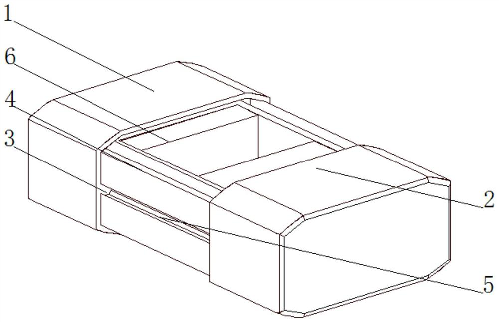
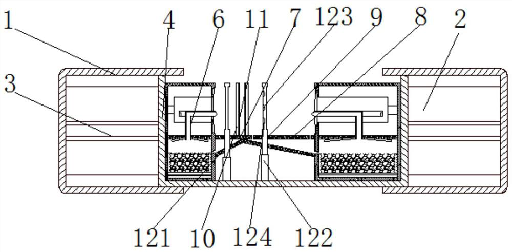
[0035] see Figure 1-2 , the present invention provides a technical solution: a spectacle case, comprising a first housing 1 and a second housing 2, both sides of the first housing 1 and the second housing 2 are fixedly connected with guide rails 3, and the guide rails 3 One side is slidably connected with a glasses storage and cleaning box 4, and both sides of the glasses storage and cleaning box 4 are provided with chutes 5, and both ends of the glasses storage and cleaning box 4 near the first casing 1 and the second casing 2 are provided with glasses Cleaning mechanism 6, one side of glasses cleaning mechanism 6 is fixedly connected with drainage connection plate 7, the top of drainage connection plate 7 is provided with first through hole 8 and second through hole 9, and drainage connection plate 7 stores cleaning box 4 near glasses The top of the side is fixedly connected with a glasses fixing rod 10, the side of the glasses fixing rod 10 is fixedly connected with a soft...

Embodiment 2

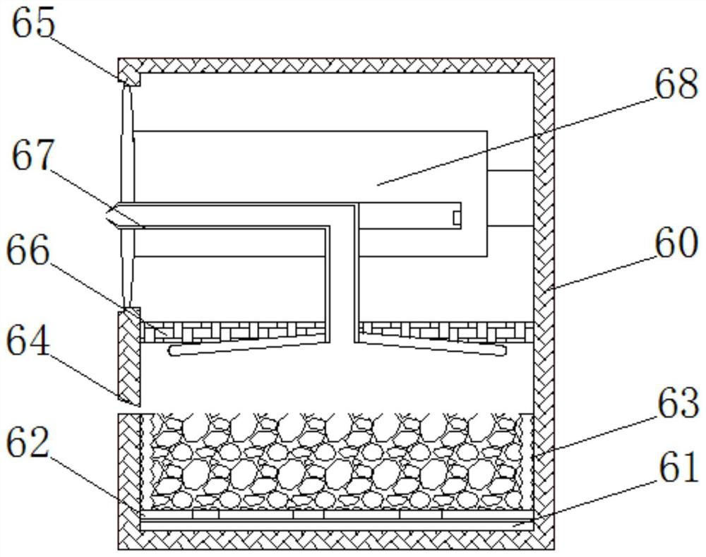
[0037] see Figure 3-6 On the basis of Embodiment 1, the present invention provides a technical solution: a glasses case, the glasses cleaning mechanism 6 includes a cleaning housing 60, the bottom of the cleaning housing 60 is fixedly connected with a first electromagnet 61, and the cleaning housing 60 is close to A magnet 62 is slidably connected to one side of the first electromagnet 61, and the side of the magnet 62 away from the first electromagnet 61 is fixedly connected to the ethanol storage box 63. mouth 64 and rectangular groove 65, the upper side of the cleaning housing 60 close to the feeding port 64 is fixedly connected with a partition plate 66, the top of the ethanol storage box 63 is provided with an ethanol spray device 67, and the ethanol spray device 67 is far away from the ethanol storage One end of the box 63 passes through the partition plate 66 and extends to the outside of the rectangular groove 65. The cleaning device 68 is slidably connected to the si...


PUM


Abstract

The invention discloses a glasses box. Guide rails are fixedly connected to the two sides of a first shell and the two sides of a second shell correspondingly, a glasses storing and cleaning box is slidably connected to one sides of the guide rails, sliding grooves are formed in the two sides of the glasses storing and cleaning box correspondingly, and glasses cleaning mechanisms are arranged at the two ends, close to the first shell and the second shell, of the glasses storing and cleaning box correspondingly; a drainage connecting plate is fixedly connected to one side of each glasses cleaning mechanism, a first through hole and a second through hole are formed in the top of the drainage connecting plate, glasses fixing rods are fixedly connected to the tops, close to the two sides of the glasses storing and cleaning box, of the drainage connecting plates, and a glasses detection device is fixedly connected to the bottom of the inner wall of the glasses storing and cleaning box; theN pole of a magnet is right opposite to the first electromagnet below, and a one-way valve is arranged in the magnet. The invention relates to the field of cleaning device. According to the glasses box, a user does not need to take down glasses for cleaning, additional auxiliary tools such as water and wiping rags are not needed, use is not affected within a short time, and time and labor are saved.

Description

technical field [0001] The invention relates to the field of cleaning devices, in particular to a spectacle case. Background technique [0002] Glasses are common items in people's daily life, especially for myopia, presbyopia and other crowds. In recent years, with the popularity of 3D movies, 3D glasses have gradually become a must-have item in movie theaters. [0003] For example, Chinese patent CN104026836B discloses a multifunctional spectacle case, which includes an electric cleaning device and a spectacle holder positioned in the spectacle case body. In the spectacle case structure, the upper bracket of the back cover and the lower bracket of the back cover are respectively connected to the upper part and the lower part of the back cover, and the front cover and the back cover are connected to form a box space for accommodating the electric cleaning device. The electric cleaning device includes a front electric cleaning device and a rear electric cleaning device resp...

Claims


Application Information

Patent Timeline
IPC IPC(8): G02C13/00
CPCG02C13/006
Inventor 刘静文
Owner 刘静文
Why Eureka
Try Eureka