
New energy automobile battery protection cover

A new energy vehicle and protective cover technology, which is applied in the direction of electric vehicles, battery pack parts, battery/battery traction, etc., can solve the problems of danger, high cost, fire, etc., and achieve protection from being squeezed and reduced Shock damage effect

Pending Publication Date: 2022-01-25
CHONGQING VOCATIONAL COLLEGE OF TRANSPORTATION
View PDF6 Cites 5 Cited by
  • Summary
  • Abstract
  • Description
  • Claims
  • Application Information

AI Technical Summary

Problems solved by technology

[0003] Most of the existing new energy vehicles completely use batteries as the energy source to drive the vehicle. Compared with traditional vehicles, the particularity of electric vehicles in collisions is reflected in the fact that high-energy, high-quality power batteries are squeezed and damaged during collisions. It may cause fire and explosion; in the battery installation of electric vehicles, the battery is generally installed on the chassis of the car, and the battery box needs to take into account the service life of the battery during the installation process. Protection, because when the car collides, the body frame is deformed, which can easily cause the body frame to squeeze the power battery from the side, resulting in the risk of internal short circuit or even fire and explosion
[0004] The current method of avoiding impact of the battery box is usually to increase the strength of the battery box shell itself, but the strength of the material itself has an upper limit, and the higher the strength, the more expensive the cost. In addition, the battery box is fixed when in use. On the chassis, this leads to the deformation of the battery box after the body is impacted and deformed, which may cause danger

Method used


Image

  • New energy automobile battery protection cover
  • New energy automobile battery protection cover
  • New energy automobile battery protection cover

Examples


Embodiment

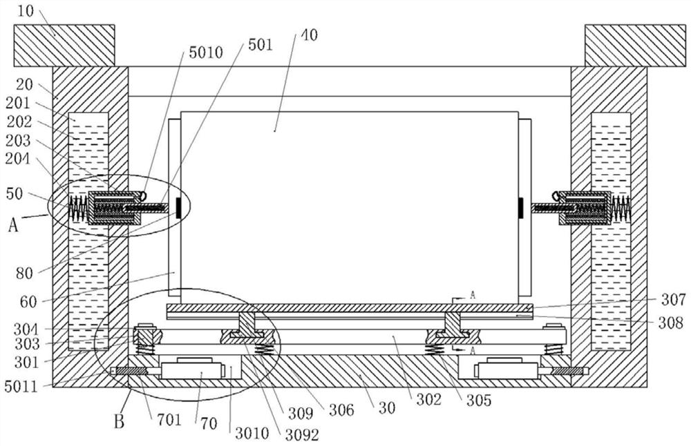
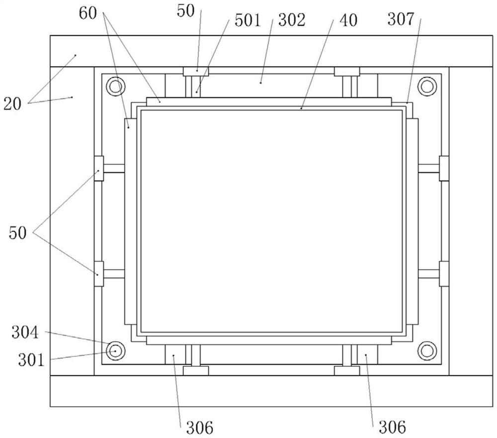
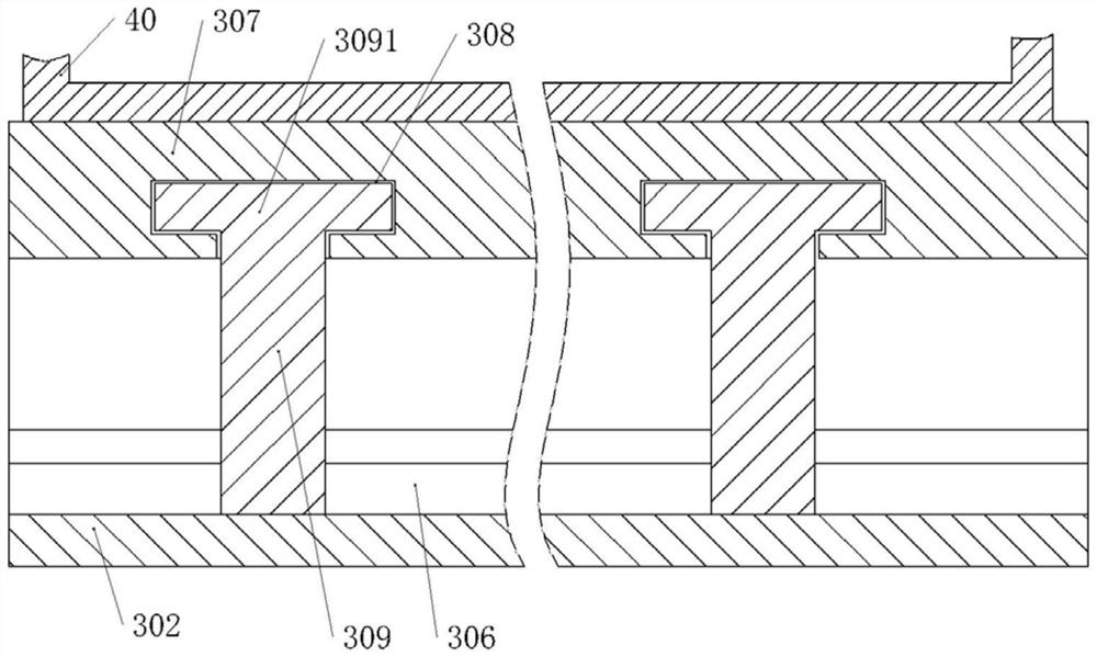
[0037] Embodiment, a kind of new energy vehicle battery protective cover, such as figure 1 , figure 2 As shown, it includes a protective box with an upper end opening and a battery box 40 located in the protective box for accommodating the battery pack. The battery box 40 is a square body that matches the battery pack of a new energy vehicle. The upper end of the protection box is fixedly connected with the automobile chassis 10, and the protection box includes vertically arranged side panels 20 and horizontally arranged bottom panels 30. Such as Figure 6 As shown, grooves 3010 are respectively set near the four corners of the bottom plate 30, and the electric cylinder 70 is fixedly connected to the groove 3010. The electric cylinder 70 is connected to an external power supply, and the telescopic rod 701 of the electric cylinder 70 is arranged horizontally along the width direction of the new energy vehicle. The side plate 20 of the box is provided with a jack 5011 that coop...


PUM


Abstract

The invention relates to the technical field of new energy automobile battery protection, in particular to a new energy automobile battery protection cover. The new energy automobile battery protection cover comprises a battery box and a protection box fixedly connected with an automobile chassis; the protection box comprises a side plate and a bottom plate; sliding columns are arranged on the bottom plate; a buffer plate is arranged above the bottom plate; first springs are vertically arranged between the buffer plate and the bottom plate; a bearing plate is horizontally arranged above the buffer plate; a plurality of connecting columns are vertically arranged between the bearing plate and the buffer plate; a cavity is formed in the side plate; non-Newtonian fluid is contained in the cavity; a second through hole and a damping cylinder are arranged on the end face of the side plate; a push rod is arranged on the damping cylinder; the outer end of the push rod is fixedly connected with a push plate; and the push plate makes contact with the outer surface of the side wall of the battery box. The new energy automobile battery protection cover has multiple buffering and damping effects on a battery and effectively protects a power battery of a new energy automobile in an automobile collision accident.

Description

technical field [0001] The invention relates to the technical field of new energy vehicle battery protection, in particular to a new energy vehicle battery protective cover. Background technique [0002] New energy vehicles refer to vehicles that use unconventional vehicle fuels as power sources, integrate advanced technologies in vehicle power control and drive, and form vehicles with advanced technical principles, new technologies and new structures. [0003] Most of the existing new energy vehicles completely use batteries as the energy source to drive the vehicle. Compared with traditional vehicles, the particularity of electric vehicles in collisions is reflected in the fact that high-energy, high-quality power batteries are squeezed and damaged during collisions. It may cause fire and explosion; in the battery installation of electric vehicles, the battery is generally installed on the chassis of the vehicle, and the battery box needs to be installed in consideration o...

Claims


Application Information

Patent Timeline
IPC IPC(8): H01M50/242H01M50/244H01M50/249B60L50/64
CPCH01M50/242H01M50/244H01M50/249B60L50/64Y02E60/10Y02T10/70
Inventor 熊如意王宏卢江林
Owner CHONGQING VOCATIONAL COLLEGE OF TRANSPORTATION
Learn More