Bidirectional drilling device for motor rotating shaft

A technology of drilling device and motor shaft, which is applied to electromechanical devices, feeding devices, positioning devices, etc., can solve the problems such as the rotation of the shaft with the drill bit, the friction force is not large enough, and the shaft is scratched, and the contact area is large and the friction force is achieved. big effect

Active Publication Date: 2022-01-28
QUANNAN CHAOYA TECH
View PDF6 Cites 0 Cited by
  • Summary
  • Abstract
  • Description
  • Claims
  • Application Information

AI Technical Summary

Problems solved by technology

[0002] In the process of motor manufacturing, the motor shaft is made by turning. The shaft is preliminarily processed from a bar blank through a lathe, and then counterbore slots are drilled at both ends of the shaft. The counterbore slots at both ends of the shaft are currently being implemented. In the process of processing, first fix one end of the shaft with a clamp, use a drilling machine to drill a hole at the protruding end of the shaft, then loosen the clamp, clamp and fix the other end of the shaft, and then use a drilling machine to drill a hole at the protruding end of the shaft. Drilling, so as to implement the drilling operation on the two ends of the rotating shaft, so the drilling operation at the two ends of the above-mentioned rotating shaft is inefficient and is not suitable for large-scale industrial production. The friction between the shaft and the shaft is not strong enough, it is easy to cause the shaft to rotate with the drill bit, resulting in the problem that the shaft is scratched by the fixture

Method used


Image

  • Bidirectional drilling device for motor rotating shaft
  • Bidirectional drilling device for motor rotating shaft
  • Bidirectional drilling device for motor rotating shaft

Examples


Embodiment Construction

[0026] Below in conjunction with accompanying drawing, the embodiment of the present invention is described in detail:

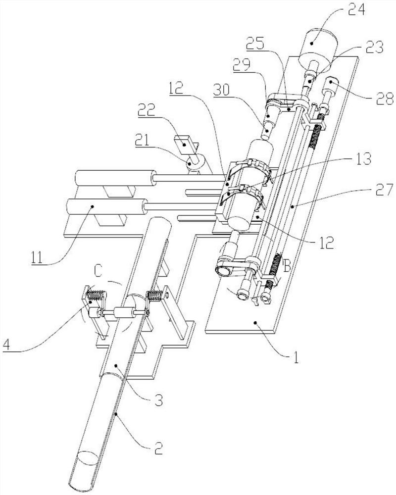
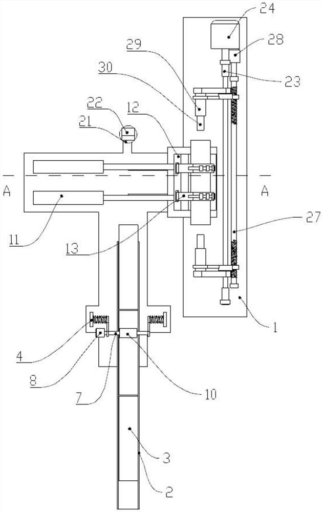
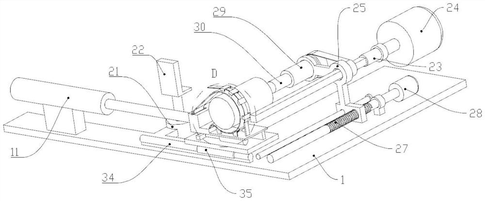
[0027] like Figure 1 to Figure 6 As shown, the present invention discloses a motor shaft bidirectional drilling device, comprising a bottom plate 1 fixed on a frame (not shown), on which a feeding tube 2 is fixed, and the bottom plate 1 at the position of the feeding tube 2 is also fixed There is a feeding device, and a plurality of feeding cylinders 11 are fixed on the bottom plate 1 at the end position of the feeding pipe 2. The ends of the piston rods of the feeding cylinders 11 are fixed to the slide table 12, and a plurality of straps 13 are fixed on the slide table 12. One end of the belt 13 is fixed with the slide table 12, and the other end of the strap 13 is fixed with the fixed block 16 after passing through the positioning groove 14 at the corresponding position on the slide table 12. There are also multiple fixed cylinders 15 fixed on the slide ...


PUM


Abstract

The invention relates to the field of motors, in particular to a bidirectional drilling device for a motor rotating shaft. The device comprises a bottom plate fixed to a rack, a feeding pipe is fixed to the bottom plate, a feeding device is further fixed to the position, at the feeding pipe, of the bottom plate, a plurality of feeding air cylinders are further fixed to the position, at the tail end of the feeding pipe, of the bottom plate, the tail ends of piston rods of the feeding air cylinders are fixed to a sliding table, a plurality of binding belts are further fixed to the sliding table, one end of each binding belt is fixed to the sliding table, the other end of each binding belt penetrates through a positioning groove in the corresponding position of the sliding table and then is fixed to a fixing block, a plurality of fixing air cylinders are further fixed to the sliding table, the tail ends of piston rods of the fixing air cylinders are fixed to the fixing block, positioning blocks are evenly fixed to the binding band, and positioning elastic pieces are fixed to the positions, corresponding to the binding band, of the sliding table. Through the device, the two ends of the rotating shaft can be punched at the same time, the production efficiency of the rotating shaft is greatly improved, and automatic punching operation of the rotating shaft is achieved.

Description

【Technical field】 [0001] The invention relates to the field of motors, in particular to a bidirectional drilling device for a motor shaft. 【Background technique】 [0002] In the process of motor manufacturing, the motor shaft is made by turning. The shaft is preliminarily processed from a bar blank through a lathe, and then counterbore slots are drilled at both ends of the shaft. The counterbore slots at both ends of the shaft are currently being implemented. In the process of processing, first fix one end of the shaft with a clamp, use a drilling machine to drill a hole at the protruding end of the shaft, then loosen the clamp, clamp and fix the other end of the shaft, and then use a drilling machine to drill a hole at the protruding end of the shaft. Drilling, so as to implement the drilling operation on the two ends of the rotating shaft, so the drilling operation at the two ends of the above-mentioned rotating shaft is inefficient and is not suitable for large-scale indu...

Claims


Application Information

Patent Timeline
Patent Type & Authority Applications(China)
IPC IPC(8): B23B41/00B23B39/22B23B47/00B23B47/22B23Q3/06H02K15/14
CPCB23B41/00B23B39/22B23B47/00B23Q5/26B23Q3/064H02K15/14Y02P70/10
Inventor 张舜黄绪海
Owner QUANNAN CHAOYA TECH
Why Eureka
Try Eureka