Park lock

A technology of parking lock and locking lever, applied in the direction of elements with teeth, belt/chain/gear, mechanical equipment, etc., to achieve the effect of long service life and simplified design

Active Publication Date: 2022-01-28
SCHAEFFLER TECH AG & CO KG
View PDF8 Cites 0 Cited by
  • Summary
  • Abstract
  • Description
  • Claims
  • Application Information

AI Technical Summary

Problems solved by technology

However, tilting due to construction is unavoidable, since otherwise the locking lever would have to be supported at the center of the shaft

Method used


Image

  • Park lock
  • Park lock
  • Park lock

Examples


Embodiment Construction

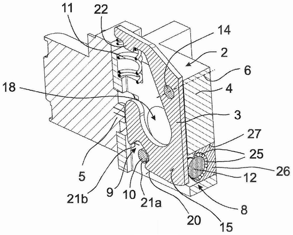
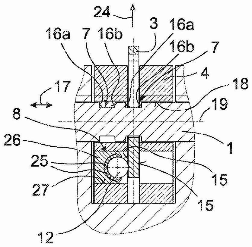
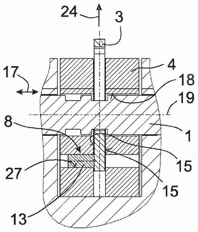
[0028] according to Figures 1 to 5 , for—not shown here—a parking lock for a motor vehicle comprising an opening that can move axially in the parking lock housing 4 and passes through the parking lock housing 4 18 switching elements 1. Furthermore, the parking lock includes a locking unit 2 which is designed to lock the axial position of the shifting element 1 relative to the parking lock housing 4 in the locked position.

[0029] The locking unit 2 of the parking lock consists in the present case of a locking lever element 3 , an actuating element 5 , a spring element 11 and a mechanism 8 for preventing the locking lever element 3 from tilting. The locking lever element 3 , which in this case consists of sheet steel, can be actuated by the actuating element 5 , which is designed as a lifting magnet, so that it pivots about a pivot axis 6 from the locking position into the unlocking position. The locking lever element 3 is substantially crescent-shaped and encloses the shif...


PUM


Abstract

The invention relates to a park lock for a motor vehicle, comprising a switching element (1) and a locking lever element (3) of a locking unit (2). The locking lever element (3) is mounted at least indirectly on a park lock housing (4) and can be actuated by an actuation element (5) in such a way that the locking lever element (3) pivots about a pivot axis (6) from a locking position to an unlocking position. In the locking position, the locking lever element (3) radially engages in a peripherally extending locking cut-out (7) in the switching element (1) in order to form-fittingly lock the switching element (1) in an axial position. The park lock has means (8) for securing the locking lever element (3) against tilting.

Description

technical field [0001] The invention relates to a parking lock for a motor vehicle, comprising a switching element and a locking lever element of a locking unit, the locking lever element being arranged for a positive fit The shifting element is locked in the axial position in the same way. Background technique [0002] The parking lock is designed to be engageable by means of a locking lever element into the shift element when actuated by the driver of the motor vehicle, so that an operative connection of the motor vehicle to the shift element can be prevented by such engagement of the locking lever element The drive shaft or driven shaft of the motor rotates, thereby preventing the motor vehicle from rolling. [0003] For example, DE 10 2015 008 709 A1 discloses a parking lock module for installation in a motor vehicle transmission, said parking lock module having at least one axially displaceable actuation cone, the actuation The cone is provided to be able to actuate a...

Claims


Application Information

Patent Timeline
Patent Type & Authority Applications(China)
IPC IPC(8): F16H63/34
CPCF16H63/3416F16H63/3458F16H63/38
Inventor 克劳斯·克拉默马蒂亚斯·费尔巴哈
Owner SCHAEFFLER TECH AG & CO KG
Why Eureka
Try Eureka