stress release roller

A stress release and roller technology, applied in the laying of tracks, roads, tracks, etc., can solve the problems of low service life, large friction coefficient of equipment, and tipping, etc., to enhance the lateral stress divergence ability, ensure free expansion and contraction, and prevent lateral slanted effect

Inactive Publication Date: 2016-04-06
郭秋亭
View PDF6 Cites 0 Cited by
  • Summary
  • Abstract
  • Description
  • Claims
  • Application Information

AI Technical Summary

Problems solved by technology

[0006] The above-mentioned patent uses the same roller and is supported by multiple bearing seats, so that the strength of the roller is increased. However, if there are many rollers, more bearing seats need to be installed, which makes the structure of the equipment complicated. A roller is set between the seats, which increases the friction between the roller and the bearing seat, resulting in a larger friction coefficient of the overall equipment. The upper edge of the roller is cooked with the upper edge of the sliding bearing seat, and when the track moves sideways, it will slide off the two sides of the roller. , causing damage to equipment and personnel
[0007] Moreover, when the two patents have the functions of preventing curve rail change, rail tipping and side shifting, etc., due to the small gap between the bearing and the bearing seat / the roller and the bearing seat (as can be seen from the drawings), the track stress adjustment construction Lateral dumping, especially in the curved section of the track change operation, is not conducive to the work, and the damage to the bearing seat and bearing / roller is greater, and the service life of the equipment is lower

Method used


Image

  • stress release roller

Examples


Embodiment Construction

[0025] The present invention will be further described below in conjunction with the accompanying drawings and specific embodiments, so that those skilled in the art can better understand the present invention, but the present invention is not limited thereby.

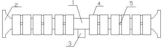
[0026] A stress relief roller, the total length of the roller is 210mm, including a roller shaft 1, the two ends of the roller shaft 1 are provided with limit plates 2, the middle part of the roller shaft 1 is provided with a support column 3, the lowest of the support column 3 end and the lowest end of the limit plate 2 are arranged on the same level, and the rollers 1 at both ends of the support column 3 are respectively provided with bearings 4, the inner diameter of the bearing 4 is 21mm, and the outer diameter of the bearing 4 is 28mm. 4 is 6, and there are 3 on both sides of the support column 3, the length of the roller 1 is greater than the total width of the bearing 4, the diameter of the roller 1 is 20mm, and ...


PUM


Abstract

The invention relates to a stress diffusion roller. The stress diffusion roller comprises a rolling shaft, wherein limiting plates are arranged at the two ends of the rolling shaft, a supporting column is arranged in the middle of the rolling shaft, bearings are arranged at the positions, at the two ends of the supporting column, of the rolling shaft respectively, the length of the rolling shaft is larger than the total width of the bearings, the diameter of the rolling shaft is 20 mm, the difference between the inner diameter of each bearing and the diameter of the rolling shaft ranges from 0.5 mm to 1 mm, and the height difference between the lowermost end of each bearing and the lowermost end of the corresponding limiting plate is 2 mm. The stress diffusion roller has the advantages that due to the facts that the bearings are arranged, strength of the rolling shaft is improved, and the supporting column is arranged, the bearing capacity of the whole stress diffusion roller is improved; due to the fact that the difference between the inner diameter of each bearing and the diameter of the rolling shaft and the height difference between the lowermost end of each bearing and the lowermost end of the corresponding limiting plate are limited, the friction coefficient of the stress diffusion roller is reduced; due to the fact that the sideward movement space is reserved, the sideward stress diffusion capacity of the stress diffusion roller is greatly improved, particularly in the curved section of rail change operation, tension of the lower strand of curves and surplus stress of the upper strand of the curves can be effectively reduced, it is ensured that a steel rail freely stretches out and draws back, and the steel rail is prevented from sideward inclination.

Description

technical field [0001] The invention relates to seamless railway laying and maintenance facilities, more specifically a stress relief drum. Background technique [0002] In recent years, the speed of trains has been increased many times, and several passenger dedicated lines have been built or are under construction. With the arrival of the climax of the construction of passenger dedicated lines and the acceleration of the transformation of existing lines, more seamless lines have been used. The construction of passenger dedicated lines has brought many conveniences to people, and seamless line technology is being more widely adopted. The welding technology requirements for long rails in the laying of seamless lines are constantly increasing. Long rail welding and stress relief are important procedures in the construction of seamless lines. stability and driving safety. [0003] Dissipating and anti-friction roller is a special tool for stress relief of seamless lines and...

Claims


Application Information

Patent Timeline
Patent Type & Authority Patents(China)
IPC IPC(8): E01B31/18
Inventor 郭秋亭蒋先栋
Owner 郭秋亭
Why Eureka
Try Eureka