Lifting equipment for building translation

A building and equipment technology, applied in the field of building translation, can solve the problems of human resource consumption, fine-tuning, and high risk, and achieve the effects of saving human resources, ensuring accuracy, and ensuring safety

Pending Publication Date: 2022-02-01
深圳市众安工程技术有限公司
View PDF5 Cites 0 Cited by
  • Summary
  • Abstract
  • Description
  • Claims
  • Application Information

AI Technical Summary

Benefits of technology

The technical effect described in this patented technology relates to an improved elevator system used at construction sites or other locations where workers are working inside buildings. This improves stability while also allowing for quick access within easy reach without having to leave them behind. It includes various components like cables, pulleys, motors, guides, rails, etc., along its way between different parts of the structure's interior space. These systems help prevent vibrations caused by movements made over uneven surfaces such as rocks or stones. Overall, these improvements improve overall performance and efficiency in managing high rise projects.

Problems solved by technology

This patented technical solution described in the text describes an issue where older methods were used on larger projects such as reconstructions or construction works due to damage caused by scraping off historic structures like houses without proper support measures. Current solutions have issues involving safety concerns over tiltrovers (the movement of the house) while elevating them up again after use. Additionally, existing lifts can cause instability if they don't fit properly into different locations around the site before moving backward.

Method used


Image

  • Lifting equipment for building translation
  • Lifting equipment for building translation
  • Lifting equipment for building translation

Examples


Embodiment Construction

[0032] In order to make the technical means, creative features, goals and effects achieved by the present invention easy to understand, the present invention will be further described below in conjunction with specific embodiments.

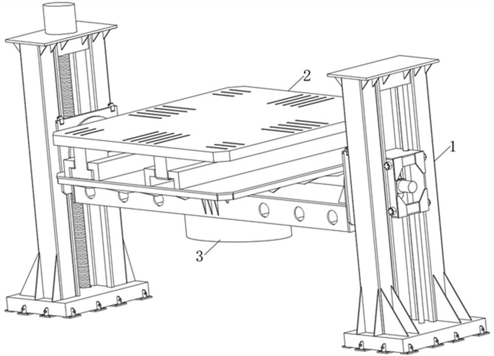
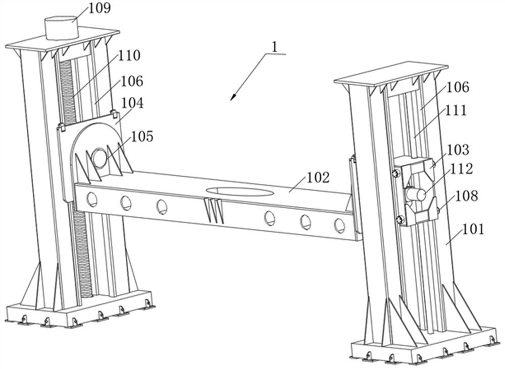
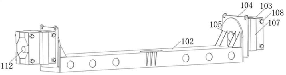
[0033] Such as Figure 1-Figure 7 As shown, a lifting device for translation of a building includes a lifting assembly 1, a displacement assembly 2 and a motor 43, the displacement assembly 2 and the motor 43 are located inside the lifting assembly 1, and the motor 43 is located at the inside of the displacement assembly 2 Below, the lifting assembly 1 includes two supporting columns 101, a supporting plate 102, two lifting frames 103 and a motor one 109, the supporting plate 102 is located between the two supporting columns 101, and the two lifting frames 103 are respectively located on the two supporting columns 101 Inside, motor one 109 is located on top of one of the support columns 101;

[0034]Wherein, the displacement assembly 2 includes c...


PUM


Abstract

The invention relates to the technical field of building translation, in particular to lifting equipment for building translation, which comprises a lifting assembly, a displacement assembly and a fourth motor, the displacement assembly and the fourth motor are both located in the lifting assembly, the fourth motor is located below the displacement assembly, and the displacement assembly comprises a second sliding groove, a third sliding groove, clamping teeth and a third motor. The second sliding groove is located on one side of the third sliding groove, and the clamping teeth are located inside the third sliding groove, the third motor is installed at one end of the third sliding groove, one end of the third motor is connected with a gear through a rotating shaft, the gear is meshed with the clamping teeth, the gear drives the clamping teeth to move left and right, and the second sliding block is matched to slide in the second sliding groove to drive a base table to move left and right. And the equipment can drive the building to move left and right, so that the building can smoothly move left and right, and the smoothness of the equipment for driving the building to move left and right is ensured.

Description


Claims


Application Information

Patent Timeline
Owner 深圳市众安工程技术有限公司
Why Eureka
Try Eureka