
Sliding turnover mechanism, headrest adjusting device and headrest bracket

A technology of a flipping mechanism and an adjusting device, which is applied in the field of furniture, can solve the problems of complex structure, difficult manufacturing and installation, poor reliability, etc. of the sliding flipping mechanism, and achieves the effects of small occupied space, reduced manufacturing and installation steps, and smooth rotational movement.

Pending Publication Date: 2022-02-08
REMACRO MASCH & TECH (WUJIANG) CO LTD
View PDF6 Cites 1 Cited by
  • Summary
  • Abstract
  • Description
  • Claims
  • Application Information

AI Technical Summary

Problems solved by technology

[0004] The technical problem to be solved by the present invention lies in the problems that the existing slide and flip mechanism for adjusting the angle of the sofa headrest has complex structure, large volume, poor reliability, and difficult manufacture and installation.

Method used


Image

  • Sliding turnover mechanism, headrest adjusting device and headrest bracket
  • Sliding turnover mechanism, headrest adjusting device and headrest bracket
  • Sliding turnover mechanism, headrest adjusting device and headrest bracket

Examples


Embodiment 1

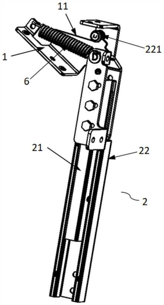
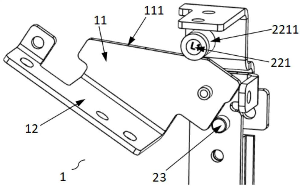
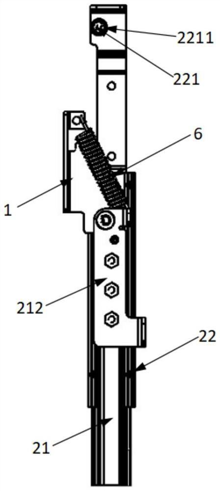
[0043] Such as Figure 1-5As shown, the present embodiment 1 provides a sliding and turning mechanism, including a turning connection part 1 and a lifting assembly 2, and the lifting assembly 2 includes a movable part 21 and a fixed part 22, the movable part 21 is used to move relative to the fixed part 22, and the turning part is connected Part 1 is used to rotate with the movable part 21; the fixed component 22 is provided with a limit deflection part 221, and the flip connector 1 is provided with a limit surface 11 matched with the limit deflection part 221, and the movable part 21 is used to drive the The turning connector 1 moves relative to the fixed assembly 22 , and when the limiting surface 11 contacts the limiting deflection member 221 , the movable member 21 continues to push to make the turning connecting member 1 rotate relative to the fixing assembly 22 .

[0044] Specifically, such as figure 2 As shown, the turning connector includes an integrally formed adjus...

Embodiment 2

[0058] Such as Figure 9 As shown, the lifting assembly 2 in the embodiment 2 is different from the embodiment 1. The difference between the lifting assembly 2 in the embodiment 2 and the embodiment 1 is that the movable part 21 is provided with a guide chute 213, and the fixed assembly 22 is provided with a guide chute. The slot 213 cooperates with the sliding part 224 , and the sliding part 224 is used for sliding connection with the guide chute 213 , and the guide chute 213 cooperates with the sliding part 224 to make the movable part 21 slide relative to the fixed assembly 22 . In Embodiment 2, the sliding member 224 is a sliding pin, at least two sliding pins are fixed on the fixed assembly 22, and the sliding pins are installed in the guide chute 213, and the guiding chute 213 is slidably connected with the sliding pin so that the movable member 21 can Sliding relative to the fixed assembly 22 .

[0059] Specifically, in this embodiment, the movable part 21 is hinged to...


PUM


Abstract

The invention discloses a sliding turnover mechanism, a headrest adjusting device and a headrest bracket. The sliding turnover mechanism comprises a turnover connecting piece and a lifting assembly, wherein the lifting assembly comprises a movable piece and a fixed assembly, the turnover connecting piece is used for being rotationally connected with the movable piece, a limiting deflection piece is arranged on the fixed assembly, a limiting surface matched with the limiting deflection piece is arranged on the turnover connecting piece, the movable piece is used for driving the turnover connecting piece to slide relative to the fixed assembly, and after the limiting surface makes contact with the limiting deflection piece, the movable piece continues pushing to enable the turnover connecting piece to rotate relative to the fixed assembly. According to the invention, the advantages of simple structure, stable movement, reduced manufacturing and mounting steps and cost saving are achieved.

Description

technical field [0001] The invention relates to the technical field of furniture, in particular to a sliding flip mechanism, a headrest adjusting device and a headrest bracket. Background technique [0002] As a part of smart home, functional sofa is becoming more and more popular in life. Functional sofas usually have the functions of adjusting posture and shape transformation. They can adjust different parts such as legs, backrest, headrest, waist, etc. to adapt to different groups of people and different sitting postures, find the most comfortable angle for the body, and relax the body. [0003] The sofas with backrest angle adjustment function in the prior art usually cannot adjust the headrest alone, or need manual adjustment, which is not convenient enough to adjust the headrest. Although some can meet the requirements of convenient adjustment, the adjustment structure is very complicated, the volume is large, the manufacture and installation are difficult, the cost i...

Claims


Application Information

Patent Timeline
Patent Type & Authority Applications(China)
IPC IPC(8): A47C17/86A47C17/04
CPCA47C17/86A47C17/04
Inventor 李晓鸿宋刚吕战征
Owner REMACRO MASCH & TECH (WUJIANG) CO LTD
Learn More