Power tool

A technology of power tools and drive shafts, which is applied in the direction of grinding workpiece supports, etc., can solve the problems of large sudden torque, impact, laborious operation, etc., and achieve reliable and firm clamping, easy operation, and strong hand feeling.

Active Publication Date: 2012-11-21
NANJING CHERVON IND
View PDF7 Cites 10 Cited by
  • Summary
  • Abstract
  • Description
  • Claims
  • Application Information

AI Technical Summary

Problems solved by technology

[0003] Although this clamping device can basically clamp the working element to the output shaft of the hand tool without auxiliary tools, this clamping device is only suitable for clamping the working element that is driven by rotation, if the working element is driven by the vibration device drive so that the working element oscillates back and forth along the longitudinal axis of the output shaft, this results in large abrupt torques in both directions of rotation and with extreme shocks, which cannot be ensured by known clamping devices Clamp the working element fully and firmly
[0004] The above-mentioned power tool in the prior art also has a defect that the working element clamped on it cannot be adjusted at multiple angles, because the working element is either in the state of being clamped and performing an operation through the clamping device, or is in the state of being clamped. In the state of releasing and taking out, when it is necessary to perform multi-angle working conditions, the working element needs to be removed and re-clamped. This operation is laborious and time-consuming, and it is not convenient enough

Method used


Image

  • Power tool
  • Power tool
  • Power tool

Examples


Embodiment Construction

[0032] The specific implementation manners of the present invention will be further described in detail below in conjunction with the accompanying drawings.

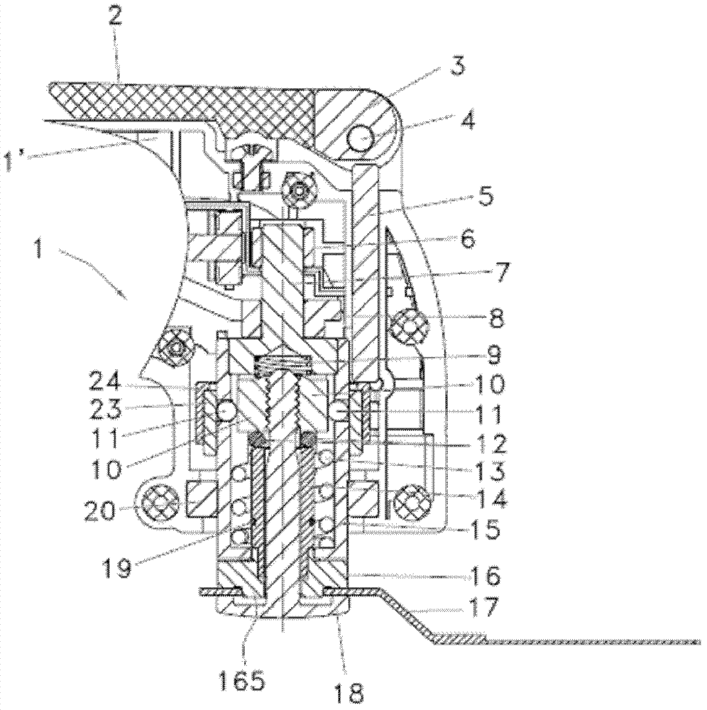
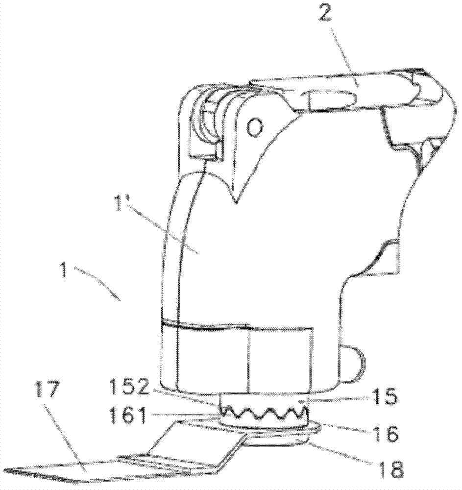
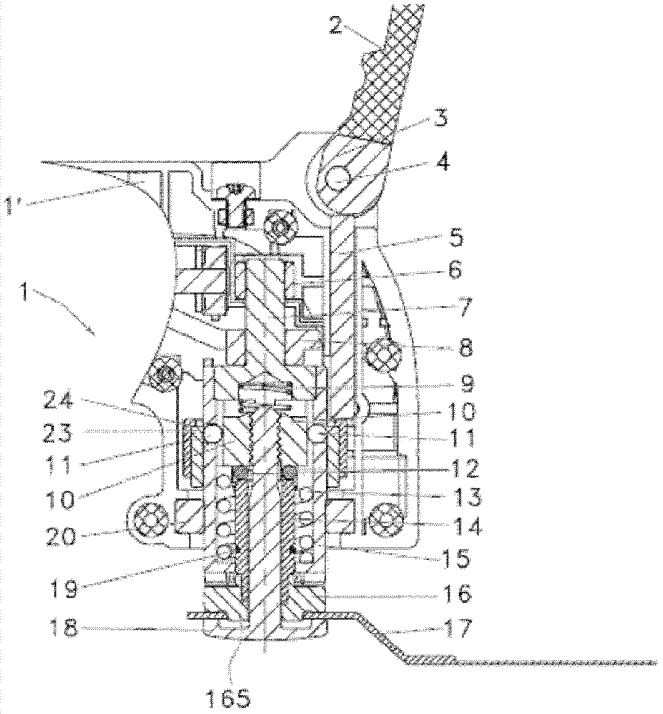
[0033] Such as Figure 1a to Figure 4c and Figure 7 As shown, the present invention is preferably described as a power tool 1 that drives the working element 17 in an oscillating manner. The power drive shaft of the power tool 1 is supported by bearings 6, 20 and rotates around its axis Y under the action of the vibrating bracket 8 in a small The reciprocating swing of the yaw angle is high-frequency, the drive shaft is configured to support the journal 7 and the hollow shaft 15, the vibration support 8 is interference-pressed on the support journal 7, and the support journal 7 and the hollow shaft 15 pass through Surplus pressure installed.

[0034] The working element 17 can be quickly clamped to the power tool 1 through the clamping mechanism, and the clamping mechanism includes a fastening element 18 and a locking...


PUM


Abstract

The invention provides a power tool which comprises a driving shaft driving a work element, a clamping mechanism, and an operating piece which is used for manual operation, wherein the clamping mechanism clamps the work element on the driving shaft, is provided with a clamping position and a releasing position, the work element is clamped on the driving shaft at the clamping position, and the work element can be taken down from the driving shaft at the releasing position; the clamping mechanism is further provided with a rotation position, the work element can rotate by an angle relative to the driving shaft at the rotation position, and the operating piece is provided with an operating position corresponding to the rotation position. Compared with the existing clamping mechanism which is only provided with the clamping position and the releasing position, angle adjustment of the work element can be carried out without taking down the work element, so that the power tool is time saving and labor saving.

Description

technical field [0001] The present invention relates to a power tool comprising an output shaft for driving the tool and a fastener for clamping a working element to the end of the output shaft, and a fastener for making the fastener A moving device that moves between a released position and a clamped position, in which the fastener can be removed from the output shaft by disengaging from the moving device, whereas in the clamped position, the fastener is locked by the moving device The joint and the elastic element work together to support the end of the output shaft so that the working element is firmly clamped. Background technique [0002] Known from US6569001B2 is a power tool with a quick clamping device, the hand tool is an angle grinder, the angle grinder is equipped with a hollow output shaft, and the hollow shaft is equipped with a Clamping device movable between a clamped position and a released position, the clamping device comprises a clamping flange with a thr...

Claims


Application Information

Patent Timeline
Patent Type & Authority Applications(China)
IPC IPC(8): B24B41/06
Inventor 周红陶
Owner NANJING CHERVON IND
Why Eureka
Try Eureka