Automatic chamfering machine

A technology of chamfering machine and chamfering mechanism, which is applied in the direction of grinding frame, grinding feed movement, and machine tools suitable for grinding the edge of workpieces, etc. It can solve the problem that the quality of workpiece chamfering is uneven and cannot be continued for a long time Continuous work, slow chamfering speed and other problems, to achieve the effect of good product quality stability, less artificial factors, and fast speed

Active Publication Date: 2014-04-23
宁波市鄞州启威机械科技有限公司
View PDF5 Cites 11 Cited by
  • Summary
  • Abstract
  • Description
  • Claims
  • Application Information

AI Technical Summary

Problems solved by technology

However, manual operation has its inherent shortcomings. On the one hand, there are many human factors, and the quality of workpiece chamfering is uneven. On the other hand, the chamfering speed is slow and the efficiency is low. The team leader chamfers the edges and cannot work continuously for a long time

Method used


Image

  • Automatic chamfering machine
  • Automatic chamfering machine
  • Automatic chamfering machine

Examples


Embodiment Construction

[0030] The present invention will be described in further detail below in conjunction with the accompanying drawings.

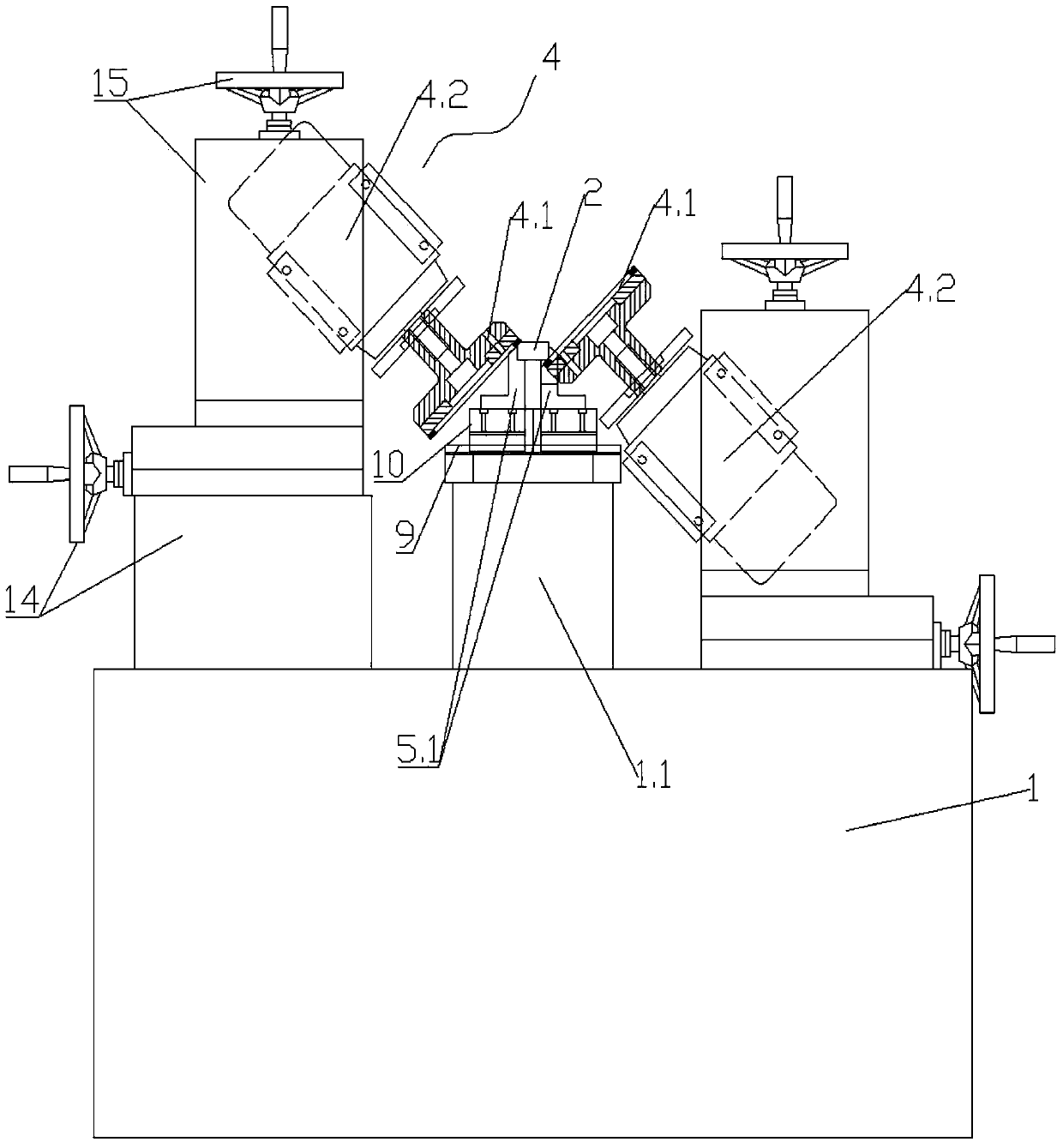
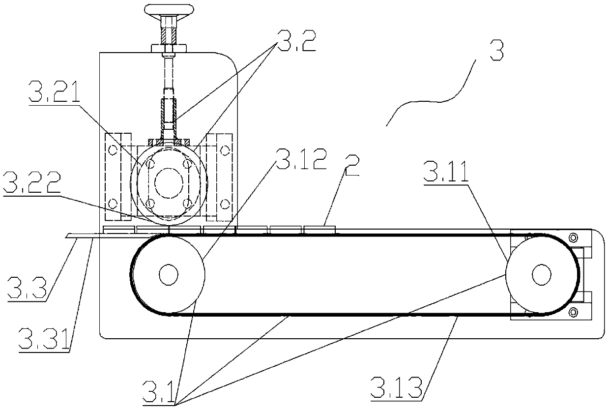
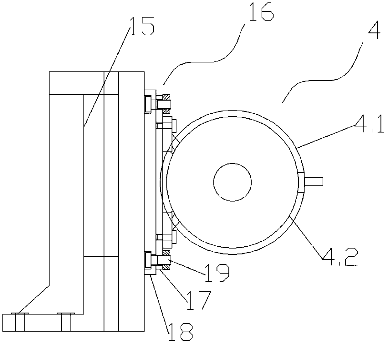
[0031] As shown in the figure, an automatic chamfering machine includes a machine base 1, a conveying mechanism 3 installed on the end of the machine base 1 and used to transport the workpiece 2, and two sets of lengths installed on the machine base 1 for the workpiece 2 Four grinding wheel chamfering mechanisms 4 for simultaneous chamfering of opposite sides 2.1, guide rail clamping mechanism 5 for clamping and smooth movement of workpiece 2 for clamping.

[0032] The guide rail clamping mechanism 5 is installed on the workbench 1.1 of the machine base 1, and the two grinding wheel chamfering mechanisms 4 are respectively located in parallel on both sides of the guide rail clamping mechanism 5 for processing a group of long pairs in the workpiece 2. Side 2.1, the other two grinding wheel chamfering mechanisms 4 are also located parallel to the two sides of t...


PUM


Abstract

The invention discloses an automatic chamfering machine. The chamfering machine comprises an engine base (1), a conveying mechanism (3), four sand wheel chamfering mechanisms (4) and a guide rail clamping mechanism (5), wherein the conveying mechanism (3) is arranged at one end of the engine base (1) and is used for conveying a work-piece (2), the four sand wheel chamfering mechanisms (4) are arranged on the engine base (1) and simultaneously chamfer the two groups of long opposite sides (2.1) of the workpiece (1), and the guide rail clamping mechanism (5) is used for clamping and smoothly moving the clamped work-piece (2) and is arranged on the working table (1.1) of the engine base (1); two of the sand wheel chamfering mechanisms (4) are respectively located at one group of long opposite sides (2.1) used for processing the work-piece (2) at the two sides of the guide rail clamping mechanism (5) in parallel, and the other two sand wheel chamfering mechanisms (4) are respectively located at the other group of long opposite sides (2.1) used for processing the work-piece (2) at the two sides of the guide rail clamping mechanism (5) in parallel. The automatic chamfering machine is not manually operated, can simultaneously chamfer the two groups of long opposite sides of the work-piece, and can continuously work for a long time segment, and has the advantages of good chamfering quality and high efficiency.

Description

technical field [0001] The invention relates to the technical field of workpiece chamfering, in particular to an automatic chamfering machine. Background technique [0002] At present, for workpieces, especially square workpieces, such as the chamfering of two sets of long opposite sides of a square magnetic block, manual chamfering is generally adopted, and a grinding wheel is used to chamfer two sets of long opposite sides one by one. However, manual operation has its inherent shortcomings. On the one hand, there are many human factors, and the quality of workpiece chamfering is uneven. On the other hand, the chamfering speed is slow and the efficiency is low. The team leader chamfers the edges and cannot work continuously for a long time. The two sets of long opposite sides actually refer to two sets of opposite sides extending along the length direction of the workpiece (a total of four opposite sides, and the number of each set of opposite sides is two). It is customar...

Claims


Application Information

Patent Timeline
Patent Type & Authority Applications(China)
IPC IPC(8): B24B9/02
CPCB24B9/02B24B41/005B24B41/02
Inventor 陈达幸
Owner 宁波市鄞州启威机械科技有限公司
Why Eureka
Try Eureka