Supercharge Your Innovation With Domain-Expert AI Agents!

Spiral cam cleaning mechanism

A cleaning mechanism and spiral cam technology, applied in the cleaning field, can solve the problems of large manpower consumption and slow cleaning speed, and achieve the effect of fast cleaning speed and good cleaning effect

Active Publication Date: 2022-02-08
深圳劲嘉新型智能包装有限公司
View PDF8 Cites 0 Cited by
  • Summary
  • Abstract
  • Description
  • Claims
  • Application Information

AI Technical Summary

Problems solved by technology

[0002] Most of the cleaning boxes on the existing market are to hold the box in one hand and the felt cloth in the other hand. The felt cloth is dipped in alcohol and rubbed back and forth several times to achieve the cleaning effect. This cleaning method requires a lot of manpower and the cleaning speed is slow.

Method used


Image

  • Spiral cam cleaning mechanism
  • Spiral cam cleaning mechanism
  • Spiral cam cleaning mechanism

Examples


Embodiment 1

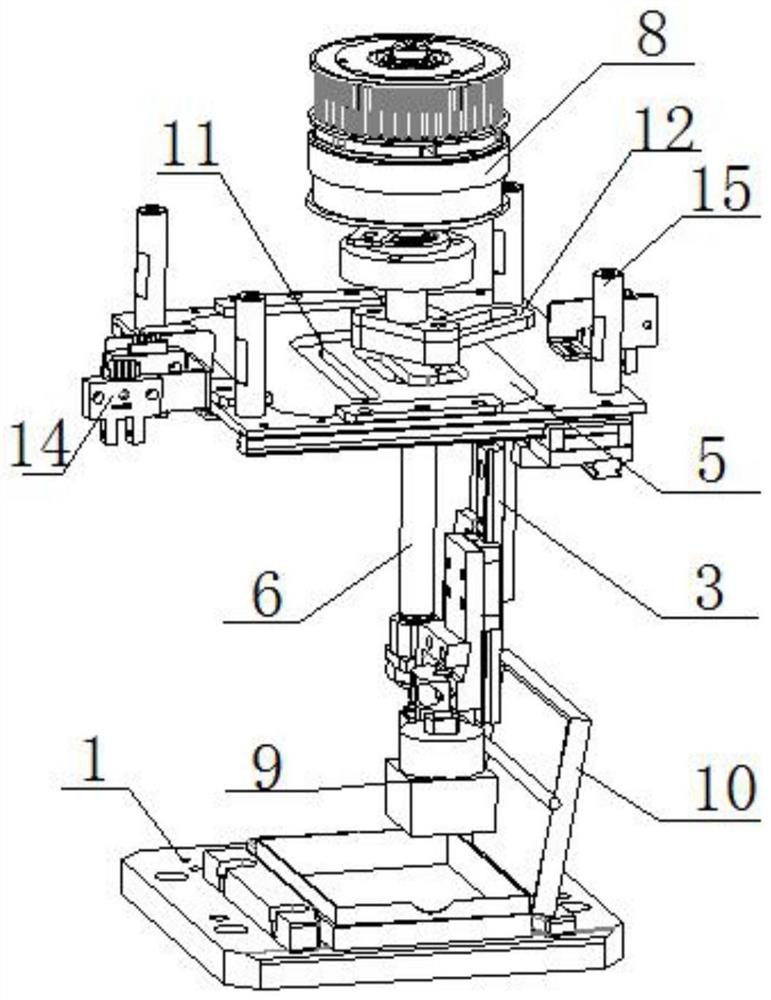
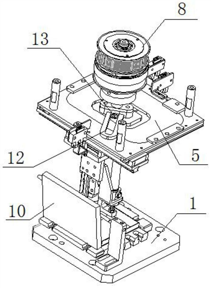
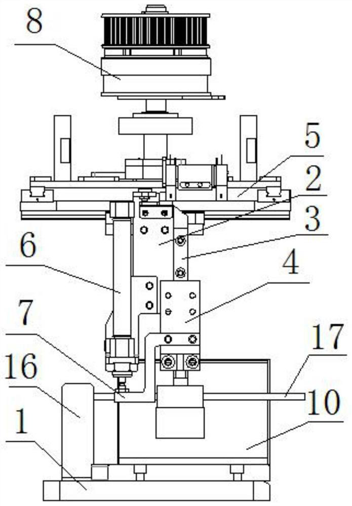
[0021] refer to Figure 1-5 , a spiral cam cleaning mechanism, including a base 1, a top plate is arranged above the base 1, a cam plate 5 is installed at the center of the top plate, a connecting plate 2 is fixedly connected to the bottom of the top plate, and a connecting plate 2 is slidably installed on one side of the connecting plate 2 Sliding block 4, the top of the sliding block 4 is equipped with a hair wheel 9, the hair wheel is pressed down by the linear motion of the line rail through the single-acting cylinder to press down the product box, one side of the connecting plate 2 is fixedly installed with an L-shaped frame, and the L-shaped frame A single-acting cylinder 6 is fixedly installed on the top, the output end of the single-acting cylinder 6 extends to the bottom of the L-shaped frame, and a Z-shaped connector 7 is fixedly connected, and the Z-shaped connector 7 is fixedly installed on one side of the sliding block 4. The top of the cam plate 5 is provided wit...

Embodiment 2

[0030] refer to Figure 1-5 , a spiral cam cleaning mechanism, including a base 1, a top plate is arranged above the base 1, a cam plate 5 is installed at the center of the top plate, a connecting plate 2 is fixedly connected to the bottom of the top plate by bolts, and the connecting plate 2 slides on one side A sliding block 4 is installed, and a hair wheel 9 is installed on the top of the sliding block 4. One side of the connecting plate 2 is fixed with an L-shaped frame by bolts, and a single-acting cylinder 6 is installed on the L-shaped frame by bolts. The output end of the output end extends to the bottom of the L-shaped frame, and is fixedly connected with a Z-shaped connector 7 by bolts, and the Z-shaped connector 7 is fixed on one side of the sliding block 4 by bolts, and an electromagnetic clutch is arranged above the cam plate 5 8. A cam swing arm 12 is attached to the bottom of the electromagnetic clutch 8, and a cam 13 is installed on the top of the connecting pl...


PUM


Abstract

The invention discloses a spiral cam cleaning mechanism which comprises a base, a top plate is arranged above the base, a cam plate is mounted in the center of the top plate, a connecting plate is fixedly connected to the bottom of the top plate, a sliding block is slidably mounted on one side of the connecting plate, and a bristle wheel is mounted at the top of the sliding block. An L-shaped frame is fixedly installed on one side of the connecting plate, a single-acting air cylinder is fixedly installed on the L-shaped frame, the output end of the single-acting air cylinder extends to the position below the L-shaped frame and is fixedly connected with a Z-shaped connecting piece, the Z-shaped connecting piece is fixedly installed on one side of a sliding block, an electromagnetic clutch is arranged above the cam plate, a cam swing arm is attracted to the bottom of the electromagnetic clutch, a cam is installed on the top of the connecting plate, and the cam sequentially penetrates through the cam plate and the cam swing arm. The bristle wheel rotates along with a cam follower to wipe a box, the cleaning purpose is achieved, the cleaning speed is high, and the cleaning effect is good.

Description

technical field [0001] The invention relates to the technical field of cleaning, in particular to a spiral cam cleaning mechanism. Background technique [0002] Most of the cleaning boxes on the existing market are to hold the box in one hand and the felt cloth in the other hand. The felt cloth is dipped in alcohol and wiped back and forth several times to achieve the cleaning effect. This cleaning method requires a lot of manpower and the cleaning speed is slow. Contents of the invention [0003] Based on the technical problems existing in the background technology, the present invention proposes a spiral cam cleaning mechanism. [0004] A spiral cam cleaning mechanism proposed by the present invention includes a base, a top plate is arranged above the base, a cam plate is installed at the center of the top plate, a connecting plate is fixedly connected to the bottom of the top plate, and the connecting plate slides on one side A sliding block is installed, the top of th...

Claims


Application Information

Patent Timeline
Patent Type & Authority Applications(China)
IPC IPC(8): B08B9/36
CPCB08B9/36
Inventor 刘朝华潘锡桂
Owner 深圳劲嘉新型智能包装有限公司
Features
  • R&D
  • Intellectual Property
  • Life Sciences
  • Materials
  • Tech Scout
  • Unparalleled Data Quality
  • Higher Quality Content
  • 60% Fewer Hallucinations
Learn More