Battery car speed reduction energy recovery system
A technology of energy recovery and battery car, which is applied in the direction of electric braking system, electric vehicle, vehicle parts, etc., can solve the problems of wasting electricity, not able to recover energy, and easy to waste energy, etc., and achieve the effect of reducing energy recovery
- Summary
- Abstract
- Description
- Claims
- Application Information
AI Technical Summary
Problems solved by technology
Method used
Image

Examples
Embodiment 1
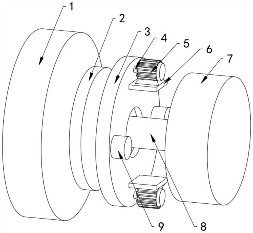
[0029] Example 1, please refer to figure 1 , comprising an axle 8, one end of the axle 8 is rotatably connected to a wheel 1, one side of the wheel 1 is provided with a brake disc 2, the side of the brake disc 2 away from the wheel 1 is provided with a brake hub 3, and the side of the brake hub 3 away from the brake disc 2 Both the top and the bottom of the side are provided with a first generator 5, the side of the axle 8 away from the wheel 1 is rotationally connected with an energy recovery device 7, the side of the brake hub 3 close to the brake disc 2 is provided with a groove, and the diameter of the groove is larger than that of the brake disc. The diameter of the disc 2, the side of the brake hub 3 away from the brake disc 2 is provided with two fixed blocks 9 along the horizontal direction, and the top and bottom inner walls of the groove provided by the brake hub 3 are provided with holes that penetrate and extend to the right side of the brake hub 3. The first rotat...
Embodiment 2
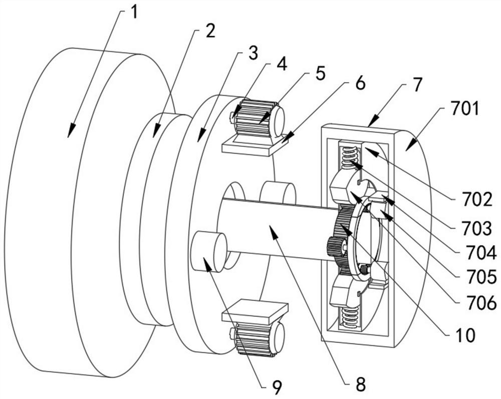
[0030] Example 2, please refer to figure 2 , 3 , 4, the energy recovery device 7 includes a first round table 701, a second round table 702, a telescopic spring 703, a fixed plate 704, a second generator 705, a movable block 706, a slide block 707, a second rotating shaft 708, an arc block 709, The connecting column 710, the first gear 711, the teeth 712, the second gear 713, the first circular platform 701 and the second circular platform 702 are all provided with cavities, and the axle 8 runs through and extends to the inside of the first circular platform 701, and is connected with the first circular platform. 701 is rotationally connected, the axle 8 is located in the cavity of the second round platform 702, and the outer ring on one side is provided with a gear ring 10, and the side walls on both sides of the cavity of the second round platform 702 are provided with slide grooves, and the slider 707 is placed on the second round platform In the chute provided by the sid...
Embodiment 3
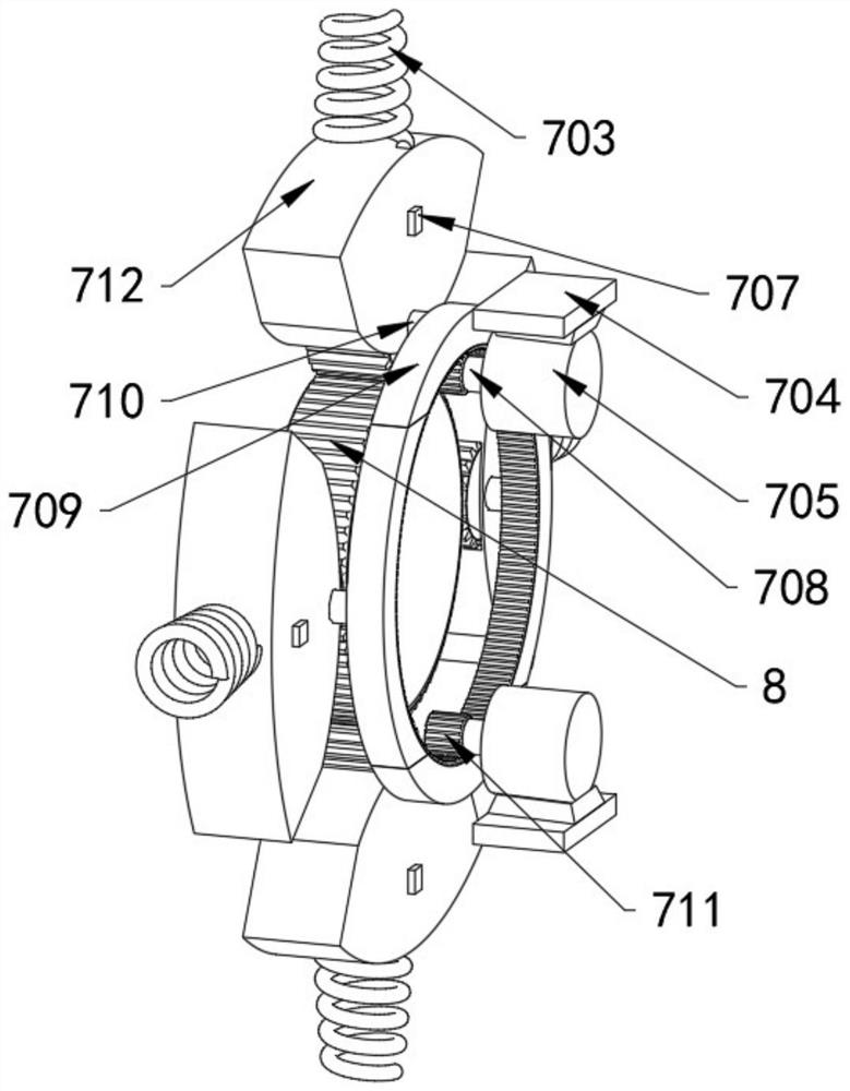
[0031] Embodiment three, please refer to figure 2 , 3, 4, the top of the cavity inner wall of the second round table 702 is welded with one end of the telescopic spring 703, the other end of the telescopic spring 703 is welded with the top of the movable block 706, the second gear 713 is installed at the bottom of the movable block 706, and is connected with the movable block 706 When the battery car decelerates, the movable block 706 will be pressed against the elastic potential energy of the telescopic spring 703, and the movable block 706 will be squeezed to move to the center of the second round platform 702. At the same time, the second gear 713 provided at the bottom of the movable block 706 will mesh with the ring gear 10, and one end of the connecting column 710 is welded on the side wall of the movable block 706, and the other end of the connecting column 710 is connected to one end of the arc block 709. Side welding, the teeth 712 are arranged at the bottom of the ...
PUM
 Abstract
Description
Claims
Application Information
 - R&D
- Intellectual Property
- Life Sciences
- Materials
- Tech Scout
- Unparalleled Data Quality
- Higher Quality Content
- 60% Fewer Hallucinations
Browse by: Latest US Patents, China's latest patents, Technical Efficacy Thesaurus, Application Domain, Technology Topic, Popular Technical Reports.
© 2025 PatSnap. All rights reserved.Legal|Privacy policy|Modern Slavery Act Transparency Statement|Sitemap|About US| Contact US: help@patsnap.com