Supercharge Your Innovation With Domain-Expert AI Agents!

Micro-particle acceleration device based on MEMS technology

A technology of accelerating devices and microparticles, which is applied in the direction of measuring devices, improvement of process efficiency, testing of machine/structural components, etc., can solve problems that have not been quantitatively supported by physical theories and have not been directly observed

Active Publication Date: 2022-02-08
SHANGHAI JIAO TONG UNIV
View PDF22 Cites 0 Cited by
  • Summary
  • Abstract
  • Description
  • Claims
  • Application Information

AI Technical Summary

Problems solved by technology

However, these putative mechanisms have not been quantitatively supported by physical theory, nor have they been directly observed

Method used


Image

  • Micro-particle acceleration device based on MEMS technology
  • Micro-particle acceleration device based on MEMS technology
  • Micro-particle acceleration device based on MEMS technology

Examples


Embodiment Construction

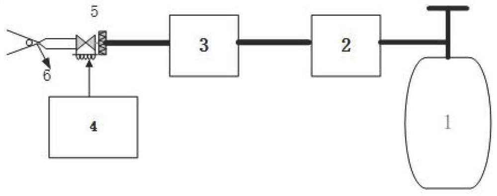
[0017] Such as figure 1 As shown, this embodiment relates to a microparticle accelerator based on MEMS technology, including: a high-pressure gas storage tank 1, a pressure reducing valve 2, a gas regulator 3, a solenoid valve drive control circuit 4, and a solenoid valve 5 connected in sequence . Miniature Lava micro-acceleration tube 6, wherein: after the gas regulator produces a stable air pressure, the electromagnetic valve is opened, and the microparticles are quickly ejected from the acceleration tube. The solenoid valve driving board is used to apply the driving voltage to the solenoid valve, shorten the time from the solenoid valve command to the actual time, and realize the millisecond pulse width injection.

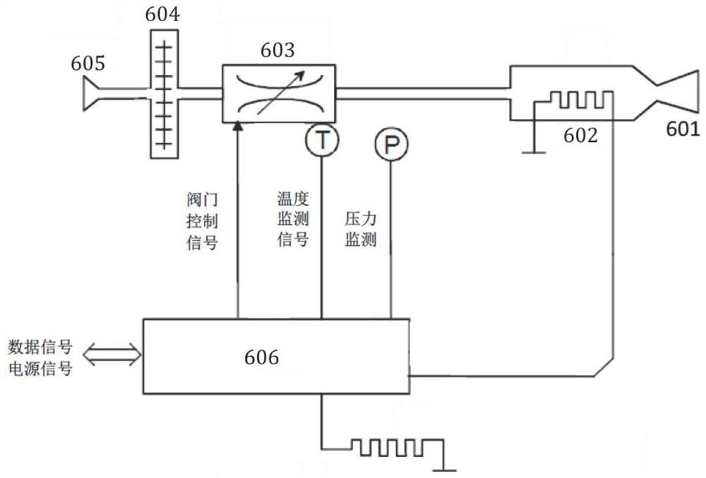
[0018] Such as figure 2 and image 3 As shown, the micro-Lava micro-accelerator tube 6 includes: a housing 607, a coiled heating chip array 602 disposed inside it, flow control valves 603 respectively disposed at the inlet and outlet ends of the housing, nozz...


PUM


Abstract

A micro-particle acceleration device based on an MEMS technology comprises a high-pressure gas storage tank, a pressure reducing valve, a gas pressure stabilizer, an electromagnetic valve driving control circuit, an electromagnetic valve and an MEMS micro acceleration tube which are sequentially connected, the particle emission speed can be accurately controlled, and a scientific research platform suitable for a laboratory range is provided for research of the impact phenomenon of micro-particles. The device has the advantages of being small in size, low in power consumption, light in weight, high in integration degree, low in cost and the like, the acceleration speed of the microparticles can be accurately controlled, and practicability is high.

Description

technical field [0001] The invention relates to a technique in the field of microparticle detection, in particular to a microparticle accelerator based on MEMS technology. Background technique [0002] Understanding the behavior of matter under high-velocity impact is key to addressing fundamental questions ranging from asteroid impacts and geological fractures to impact-induced phase transitions, spallation, wear and ballistic penetration. Studying the supersonic impact of individual metal particles on a substrate at microscale and nanosecond resolution allows direct observation of the material-dependent threshold velocity above which the particle impacts the material causing plastic deformation and adhesion to the substrate. Not a rebound. As an alternative to high-temperature melting or sintering particles, it also opens a new window for additive manufacturing, where many metal particles can be accelerated through a supersonic nozzle and impacted onto a metal substrate t...

Claims


Application Information

Patent Timeline
Patent Type & Authority Applications(China)
IPC IPC(8): G01N3/307G01N3/02G01M7/08
CPCG01N3/307G01N3/02G01M7/08G01N2203/001G01N2203/0044G01N2203/0092Y02P10/25
Inventor 慕忠成王巍吴树范易纪元
Owner SHANGHAI JIAO TONG UNIV
Features
  • R&D
  • Intellectual Property
  • Life Sciences
  • Materials
  • Tech Scout
  • Unparalleled Data Quality
  • Higher Quality Content
  • 60% Fewer Hallucinations
Learn More