Anti-loosening hexagonal flange nut machining equipment with anti-skid teeth

A flange nut and processing equipment technology, which is applied in the field of nut processing, can solve the problems that plate punching cannot be quickly inquired and positioned, and punching and nut cannot be accurately riveted and combined, so as to achieve accurate riveting and bonding position of the positioning center, punching The effect of precise hole query and positioning, and precise riveting position

Inactive Publication Date: 2022-02-11
温州协达五金科技股份有限公司
View PDF1 Cites 0 Cited by
  • Summary
  • Abstract
  • Description
  • Claims
  • Application Information

AI Technical Summary

Problems solved by technology

[0005] This application proposes a flange nut riveting process design that can quickly complete the positioning center of the punching hole, the nut center axis and the riveting center axis synchronously. The technical problem that the punching hole and the nut cannot be accurately riveted during riveting ensures the processing quality of nut riveting products

Method used


Image

  • Anti-loosening hexagonal flange nut machining equipment with anti-skid teeth
  • Anti-loosening hexagonal flange nut machining equipment with anti-skid teeth
  • Anti-loosening hexagonal flange nut machining equipment with anti-skid teeth

Examples


Embodiment 1

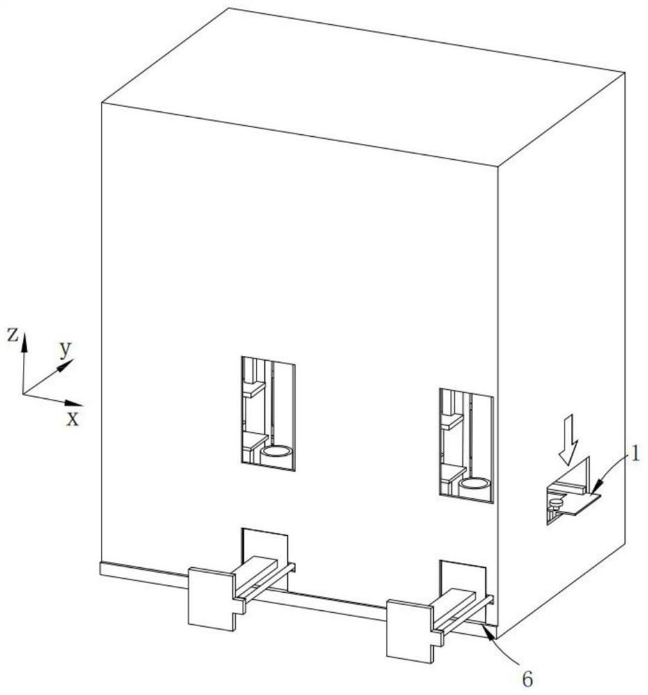
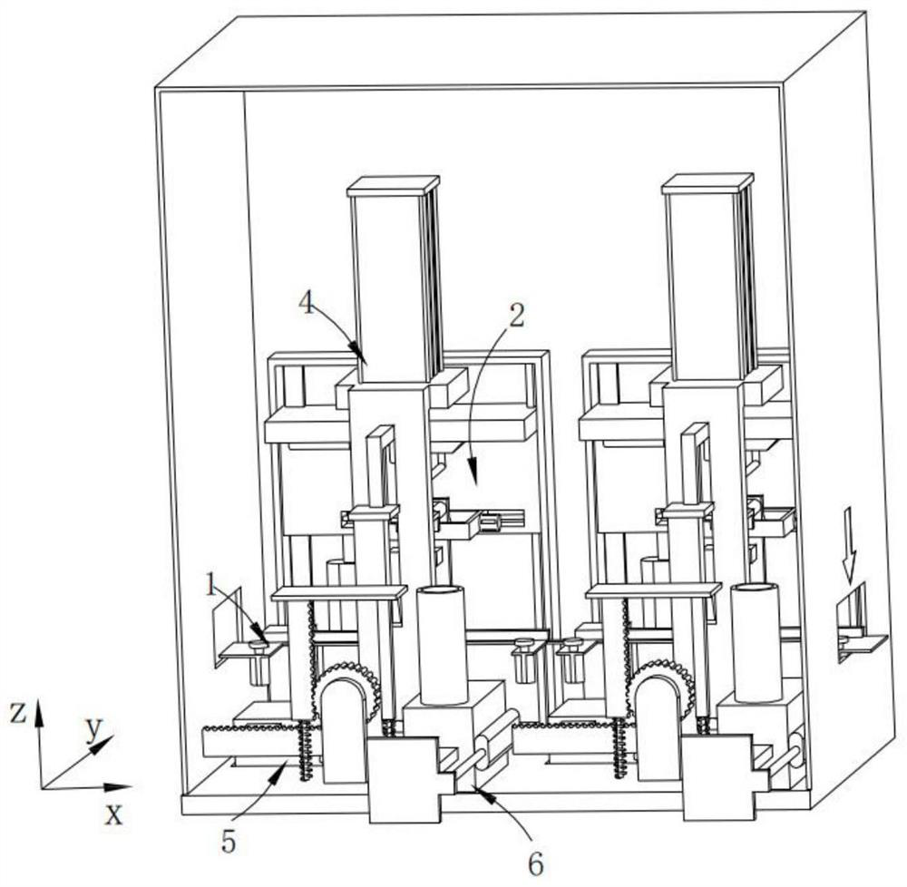
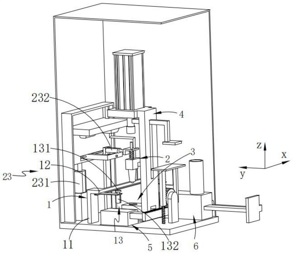
[0039] Such as Figure 1-3 As shown, a processing equipment for anti-loosening hexagonal flange nuts with anti-skid teeth, including:

[0040] Locking table 1 for keeping the plate punching position unchanged;

[0041] A positioning component 2 that is arranged above the plate and searches for and locates the punching hole of the plate;

[0042] Carry the nut and follow the positioning component 2 to the guide component 3 that is attached to the bottom of the center of the positioning punching hole;

[0043] Synchronously with the positioning assembly 2, reaching the riveting assembly 4 above the center of the positioning punching hole; and

[0044] A load-bearing component 5 provided on one side of the guide assembly 3 and supporting the bottom of the guide assembly 3 during riveting.

[0045] Through the above content, it is not difficult to find that in the process of riveting the nut and the plate, the punched plate is first placed on the locking table 1, and the punching...

Embodiment 2

[0100] Such as Image 6 As shown, the components that are the same as or corresponding to those in the first embodiment are marked with the corresponding reference numerals in the first embodiment. For the sake of simplicity, only the differences from the first embodiment will be described below. The difference between this embodiment two and embodiment one is:

[0101] The bearing assembly 5 includes:

[0102] Base 51;

[0103] sliding the support platform 52 arranged on the base 51;

[0104] Drive the supporting platform body 52 to move to the linkage part 53 at the bottom of the rising guide assembly 3; and

[0105] The power end of the riveting assembly 4 moves up and down and links the pressing part 54 of the linkage part 53 .

[0106] In this embodiment, when the riveting assembly 4 performs the riveting action downward, it will move synchronously with the pressing part 54, and when the pressing part 54 reaches the linkage part 53, it will drive the linkage part 53, ...


PUM


Abstract

The invention provides an anti-loosening hexagonal flange nut machining equipment with anti-skid teeth in the technical field of nut machining. The anti-loosening hexagonal flange nut machining equipment comprises a locking table used for keeping the punching position of a plate unchanged; a positioning assembly arranged over the plate and used for searching and positioning a punching hole of the plate; a guiding and conveying assembly which carries a nut to be tightly attached to the bottom of the center of the positioning punching hole along with the positioning assembly; a riveting assembly which reaches the position over the positioning punching center synchronous with the positioning assembly; and a force bearing assembly which is arranged at one side of the guiding and conveying assembly and supports the bottom of the guiding and conveying assembly in the riveting process. The anti-loosening hexagonal flange nut machining equipment has the advantages that the punching riveting position of the flange nut and the plate is positioned accurately, and riveting is stable.

Description

technical field [0001] The invention relates to the technical field of nut processing, in particular to a processing device for anti-loosening hexagonal flange nuts with anti-skid teeth. Background technique [0002] Rivet nuts are also called rivet nuts, self-fastening nuts, which are a kind of nuts applied to thin plates or sheet metals. They are round in shape and have embossed teeth and guide grooves at one end. The principle is to press the embossing teeth into the preset holes of the sheet metal. Generally speaking, the aperture of the preset holes is slightly smaller than the embossing teeth of the rivet nut. The periphery of the hole is plastically deformed, and the deformation is squeezed into the guide groove, thereby producing a locking effect. [0003] Chinese patent CN208467054U discloses a riveting tool for riveting nuts, including a pad, a riveting punch, a machine base and a punch driver. section, the diameter of the upper section of the guide pin is smalle...

Claims


Application Information

Patent Timeline
Patent Type & Authority Applications(China)
IPC IPC(8): B21D39/00B21D43/00B21D43/02
CPCB21D39/00B21D43/003B21D43/02
Inventor 诸晓静林晓贴杨以帖
Owner 温州协达五金科技股份有限公司
Why Eureka
Try Eureka