
Augmented reality glasses

An augmented reality and glasses technology, applied in the field of glasses, can solve the problems of relative position deviation of optical-mechanical modules, inability to meet the wearing and use of different users, and spread of temples.

Pending Publication Date: 2022-02-11
GEER TECH CO LTD
View PDF5 Cites 0 Cited by
  • Summary
  • Abstract
  • Description
  • Claims
  • Application Information

AI Technical Summary

Problems solved by technology

[0002] For augmented reality glasses products with binocular display, the problem of binocular fusion needs to be considered, and the relative position accuracy of the optical machine and the optical waveguide is relatively high; while traditional smart glasses, due to individual differences, may cause mirror damage when worn. Excessive stretching of the l

Method used


Image

  • Augmented reality glasses
  • Augmented reality glasses
  • Augmented reality glasses

Examples


Embodiment 1

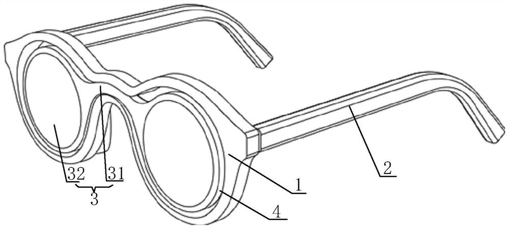
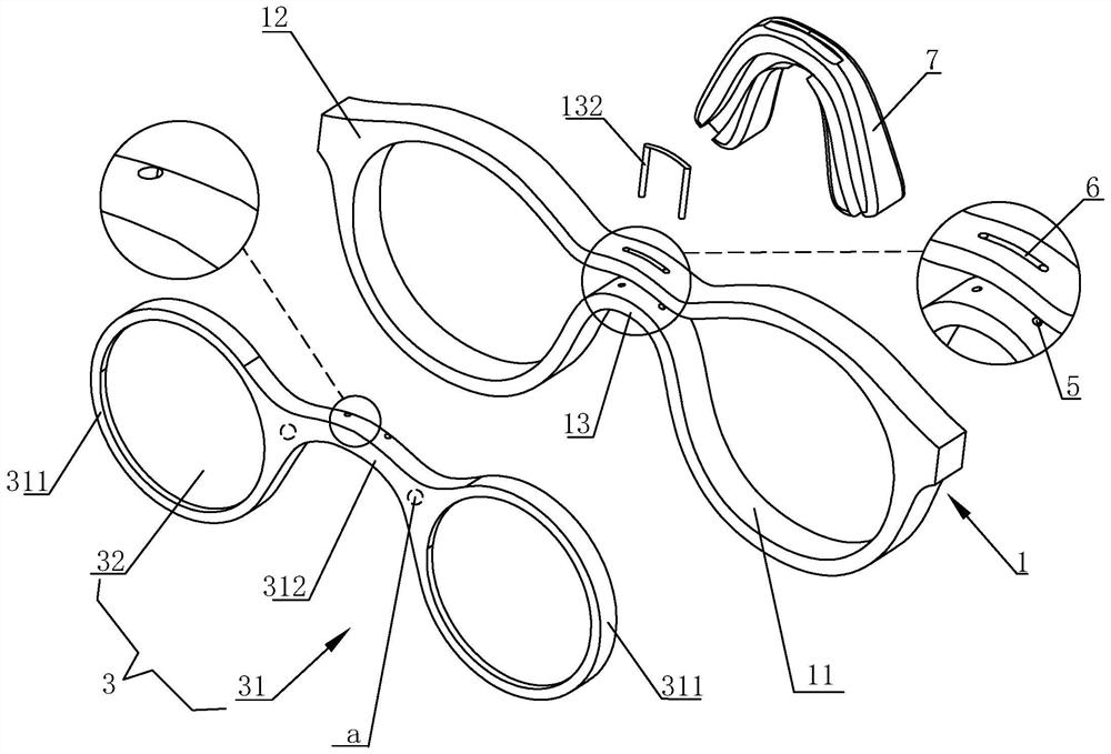
[0032] Depend on figure 1 with figure 2 Commonly shown, this embodiment discloses an augmented reality glasses, including a main mirror frame 1 , mirror legs 2 arranged at the left and right ends of the main mirror frame 1 , and an optical display assembly 3 . Wherein, the main mirror frame 1 includes a left frame body 11, a right frame body 12, and a nose bridge 13 connected between the left frame body 11 and the right frame body 12; the optical display assembly 3 includes a secondary mirror frame 31 (preferably made of an alloy material), The optical display lens 32 installed on the sub-frame 31 and the optical machine module that is installed on the sub-frame 31 and corresponds to the optical display lens 32 one by one; the sub-frame 31 includes two lens mounting parts 311 and is connected to the two lens mounting parts The connecting part 312 between the parts 311; the connecting part 312 is connected with the bridge of the nose 13, the lens mounting part 311 is located ...

Embodiment 2

[0037] The structure of this embodiment is basically the same as that of Embodiment 1, the difference lies in the way of connection between the connecting portion 312 and the bridge of the nose 13; only the differences will be described below.

[0038] Depend on Figure 4As shown, the side of the bridge of the nose 13 facing away from the face is provided with a first slot 131 for fitting and locking with the connecting portion 312 ; the main frame 1 and the secondary frame 31 are locked.

Embodiment 3

[0040] The structure of this embodiment is basically the same as that of Embodiment 1, except that the structure of the main mirror frame 1 is different, and only the differences will be described below.

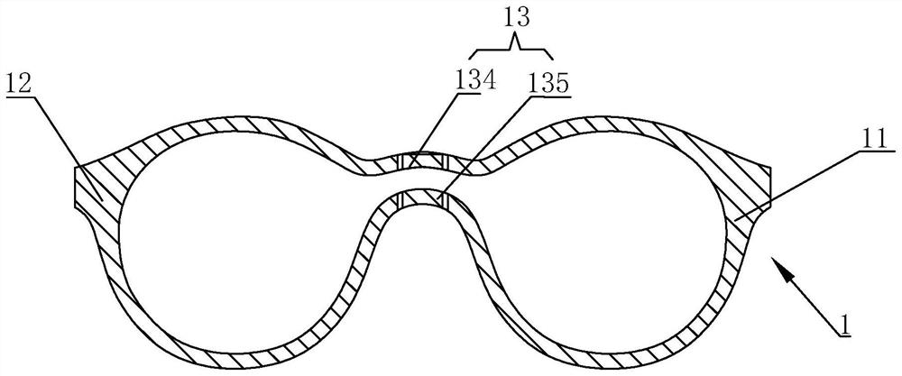
[0041] Depend on Figure 5 As shown, in this embodiment, the left frame body 11 and the right frame body 12 are connected by the nose bridge 13 to form a half-frame structure with an open lower end, that is, a half-frame structure in which the main mirror frame 1 is integrally formed. The connecting part 312 is located below the bridge of the nose 13 and is connected to the bridge of the nose 13 through a connecting piece; the connecting piece can be a fixed pin or a figure 2 The U-shaped connector 132 shown in.

[0042] Depend on Image 6 with Figure 7 As shown, in some other embodiments, the nose bridge 13 is provided with a second card slot 133 for fitting and snapping with the connecting portion 312 ; the main frame 1 is clipped with the secondary frame 31 .

[004...


PUM


Abstract

The invention discloses augmented reality glasses which comprise a main glasses frame and glasses legs arranged at the end parts of the main glasses frame, and an optical display assembly; the main glasses frame comprises a left frame body, a right frame body and a nose bridge frame connected between the left frame body and the right frame body; the optical display assembly comprises an auxiliary mirror frame, optical display lenses mounted on the auxiliary mirror frame and optical machine modules which are mounted on the auxiliary mirror frame and are in one-to-one correspondence with the optical display lenses; the auxiliary glasses frame comprises two lens mounting parts and a connecting part connected between the two lens mounting parts; the connecting part is connected with the nose bridge frame, the lens mounting part is located in the left frame body or the right frame body, and avoiding gaps are formed between the inner circumferential surface of the left frame body and the outer circumferential surface of the corresponding lens mounting part and between the inner circumferential surface of the right frame body and the outer circumferential surface of the corresponding lens mounting part. According to the invention, the relative positions of the optical machine display module and the optical waveguide are not changed during wearing, so that the accuracy of optical imaging is ensured, and the phenomenon of image offset or binocular image fusion failure is avoided; and the wearing and using requirements of different users are met.

Description

technical field [0001] The invention belongs to the technical field of glasses, in particular to augmented reality glasses. Background technique [0002] For augmented reality glasses products with binocular display, the problem of binocular fusion needs to be considered, and the relative position accuracy of the optical machine and the optical waveguide is relatively high; while traditional smart glasses, due to individual differences, may cause mirror damage when worn. Excessive stretching of the legs will cause slight deformation of the frame (optical bracket part), which will lead to deviations in the relative positions of the optical-mechanical module and the optical waveguide, making it difficult to ensure the accuracy of optical imaging, prone to image shift or binocular fusion Phenomenon, unable to meet the wearing and using of different users. Contents of the invention [0003] Aiming at overcoming at least one of the deficiencies in the above-mentioned prior art...

Claims


Application Information

Patent Timeline
IPC IPC(8): G02B27/01G02C5/02
CPCG02B27/017G02B27/0176G02C5/02G02B2027/0178
Inventor 毕贤刚于洋
Owner GEER TECH CO LTD
Learn More