
Anti-disengaging bridge support and bridge adopting same

A bridge support and anti-detachment technology, which is applied to bridges, bridge parts, bridge materials, etc., can solve the problems of high cost of bearing replacement, damage to the upper structure, and large social impact, so as to ensure safety, prolong service life, and prevent Effect of disease

Pending Publication Date: 2022-02-15
中冶南方城市建设工程技术有限公司 +1
View PDF7 Cites 0 Cited by
  • Summary
  • Abstract
  • Description
  • Claims
  • Application Information

AI Technical Summary

Problems solved by technology

Once the void occurs, it is usually necessary to replace the empty support. During the replacement, the traffic needs to be interrupted, the beam body should be lifted, and the support pad stone should be poured again. The cost of replacing the support is high, the construction period is long, and the social impact is great. , and when the support void occurs, usually the damage to the superstructure has already occurred

Method used


Image

  • Anti-disengaging bridge support and bridge adopting same
  • Anti-disengaging bridge support and bridge adopting same

Examples


Embodiment 1

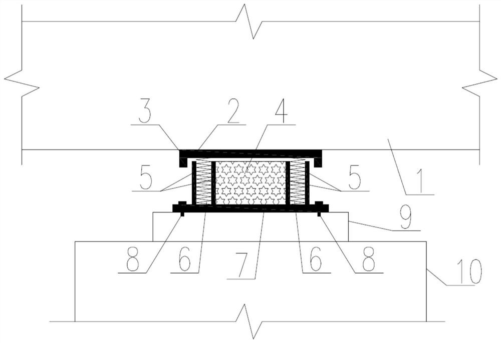
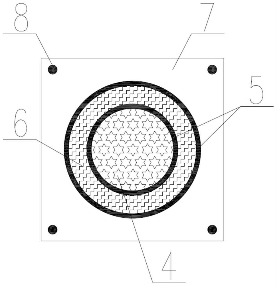
[0037] see figure 1 and figure 2 , a kind of anti-vacation bridge support, placed between the beam body 1 of the bridge superstructure and the bridge substructure 10, it includes the upper steel plate 2 of the support, the lower steel plate 7 of the support, the support stone 9, and the double-layer annular seal Steel plate 5, buffer component 4, elastic component 6. The steel plate 2 on the support is fixed on the beam body 1 of the bridge superstructure; anchor bolts 8 are arranged around the steel plate 7 under the support, and the anchor bolts 8 fix the steel plate 7 under the support on the support pad stone 9, and the support pad stone 9 is fixed on the bridge substructure 10. The double-layer annular sealing steel plate 5 is placed between the upper steel plate 2 of the support and the lower steel plate 7 of the support, its lower end is fixed on the lower steel plate 7 of the support, and there is a gap between the upper end and the upper steel plate 2 of the suppor...

Embodiment 2

[0040] The difference from Example 1 is that in order to better limit the vertical and horizontal displacement of the bridge, prevent excessive vertical and horizontal displacement, and prevent the occurrence of the anti-vacation phenomenon, according to the displacement requirements of the bridge, around the steel plate 2 on the support Set the limit plate 3.

[0041] In the present invention, the thickness of the steel plate 2 on the support and the steel plate 7 under the support is 20-40mm.

Embodiment 3

[0043] A kind of bridge, this bridge adopts embodiment 1 or embodiment 2 anti-vacation bridge support.


PUM

PropertyMeasurementUnit
Thicknessaaaaaaaaaa

Abstract

The invention discloses an anti-disengaging bridge support which comprises an upper support steel plate, a lower support steel plate, a double-layer annular sealing steel plate, a buffering component and an elastic component. The support upper steel plate is fixed on a bridge superstructure beam body; the support lower steel plate is fixed on a bridge lower structure; the lower end of the double-layer annular sealing steel plate is fixed on the support lower steel plate, and a gap is formed between the upper end and the support upper steel plate; the buffering component is arranged in the inner ring of the double-layer annular sealing steel plate, one end of the buffering component is fixed with the support lower steel plate, and a gap is formed between the other end and the support upper steel plate; the elastic component is in close fitting with the inner and outer steel plates of the double-layer annular sealing steel plate; the upper end of the elastic component is fixedly connected with the support upper steel plate, and the lower end of the elastic component is fixedly connected with the support lower steel plate. The invention further discloses a bridge adopting the anti-disengaging bridge support. The support can be prevented from disengaging, the upper structure of the bridge is always in a supported state, the safety of the bridge structure is ensured, and normal use of the bridge structure is guaranteed.

Description

technical field [0001] The invention belongs to the technical field of bridge construction, and in particular relates to a hollow-proof bridge support and a bridge using the support. Background technique [0002] The bridge bearing is an important structural component connecting the upper structure and the lower structure of the bridge. It is located between the bridge and the pad stone. It can reliably transmit the load and deformation (displacement and rotation angle) borne by the upper structure of the bridge to the lower structure of the bridge. The important force transmission device of the bridge plays a vital role in the normal use of the bridge. [0003] Due to the deflection of the beam body, the lack of flatness and strength of the support pad stone, the large number of transverse supports, and the super static stability of the upper structure, etc., the support often appears empty during installation and use. . Bridge bearing void is a common and serious disease...

Claims


Application Information

Patent Timeline
IPC IPC(8): E01D19/04E01D101/30E01D101/40
CPCE01D19/041E01D2101/30E01D2101/40
Inventor 王存刘宇闻万家恺陈维程建波王雪萍武创
Owner 中冶南方城市建设工程技术有限公司
Learn More