Tension detection mechanism for yarn strength

A detection mechanism, yarn strength technology, applied in the direction of strength characteristics, the use of stable tension / pressure test material strength, measuring devices, etc., can solve the problem of inaccurate detection, difficult control of force intensity, and yarn force Unbalanced and other problems, to achieve the effect of accurate tension detection, easy detection, and convenient installation

Inactive Publication Date: 2022-02-15
安徽汀州工程科技有限公司
View PDF0 Cites 4 Cited by
  • Summary
  • Abstract
  • Description
  • Claims
  • Application Information

AI Technical Summary

Problems solved by technology

[0002] In the textile field, it is necessary to test the strength of the yarn, especially some sportswear has high requirements on the strength of the fabric, so the tension of the yarn needs to be tested before spinning. The current method of testing the tension of the yarn is , is to detect the tension of the yarn by pulling the two ends of the yarn to move to the outside, and through the distance that the two ends of the yarn move. Although this method can detect the tension of the yarn, the force on the yarn is not balanced, and The force intensity is difficult to control, resulting in inaccurate detection, so we propose a tension detection mechanism for yarn strength to solve the above problems

Method used


Image

  • Tension detection mechanism for yarn strength
  • Tension detection mechanism for yarn strength
  • Tension detection mechanism for yarn strength

Examples


Embodiment Construction

[0023] The following will clearly and completely describe the technical solutions in the embodiments of the present invention with reference to the accompanying drawings in the embodiments of the present invention. Obviously, the described embodiments are only some, not all, embodiments of the present invention. Based on the embodiments of the present invention, all other embodiments obtained by persons of ordinary skill in the art without making creative efforts belong to the protection scope of the present invention.

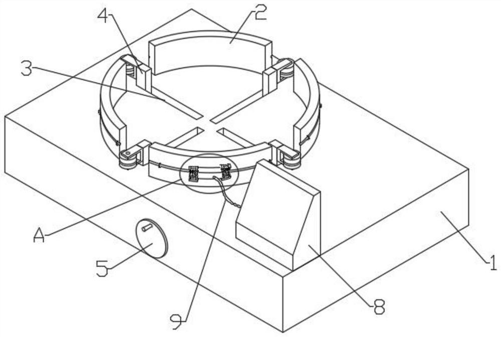
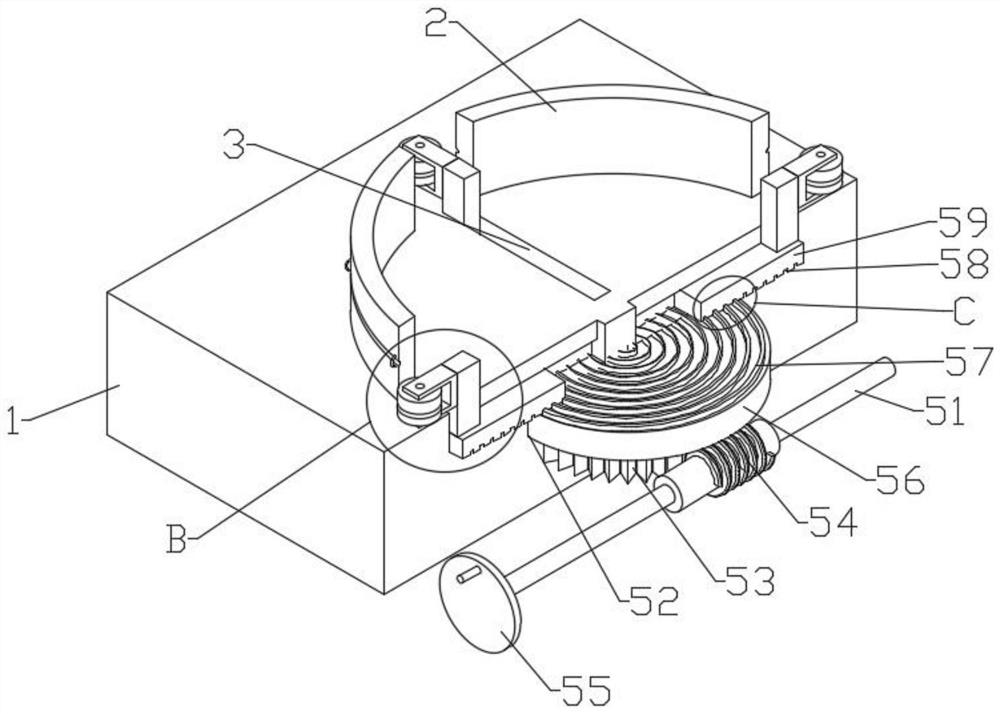
[0024] see Figure 1-5 , the present invention provides a technical solution: a tension detection mechanism for yarn strength, including a base 1, a plurality of winding boards 2 are fixedly installed on the base 1, and on the base 1 between adjacent winding boards 2 A chute 3 is opened, and the compression head 4 is slid and clamped in the chute 3. A pressure applying mechanism 5 is installed in the base 1. The pressure applying mechanism 5 is connected to th...


PUM


Abstract

The invention discloses a tension detection mechanism for yarn strength. The mechanism comprises a base, a plurality of winding plates are fixedly mounted on the base, a sliding groove is formed in the base between adjacent winding plates, a pressing head is slidably clamped in the sliding groove, a pressure applying mechanism is mounted in the base, the pressure applying mechanism is connected with the pressing head, a tension sensor is fixedly mounted on the outer wall of one winding plate, clamping mechanisms are installed at the two ends of the tension sensor, a display screen is fixedly installed on the base, and a connecting line is installed between the display screen and the tension sensor. Yarn is wound on the multiple winding plates and sequentially penetrates through the multiple pressing heads, then the two ends of the yarn are fixedly clamped to the two ends of the tension sensor through the clamping mechanisms respectively, and the multiple pressing heads are driven by the pressure applying mechanism to synchronously move, so the multiple pressing heads evenly apply pressure to the yarn in a segmented mode till the yarn is broken; and the yarn tension strength can be detected through the tension sensor, the detection is convenient, the force application strength can be slowly applied, and the detection precision is high.

Description

technical field [0001] The invention relates to the technical field of textiles, in particular to a tension detection mechanism for yarn strength. Background technique [0002] In the textile field, it is necessary to test the strength of the yarn, especially some sportswear has high requirements on the strength of the fabric, so the tension of the yarn needs to be tested before spinning. The current method of testing the tension of the yarn is , is to detect the tension of the yarn by pulling the two ends of the yarn to move to the outside, and through the distance that the two ends of the yarn move. Although this method can detect the tension of the yarn, the force on the yarn is not balanced, and The force intensity is difficult to control, resulting in inaccurate detection, so we propose a tension force detection mechanism for yarn strength to solve the above problems. Contents of the invention [0003] The object of the present invention is to provide a tension detec...

Claims


Application Information

Patent Timeline
Patent Type & Authority Applications(China)
IPC IPC(8): G01N3/08
CPCG01N3/08G01N2203/0003G01N2203/0017G01N2203/028G01N2203/0067G01N2203/0676
Inventor 陈华
Owner 安徽汀州工程科技有限公司
Why Eureka
Try Eureka