

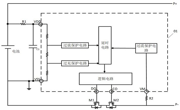
A battery protection circuit and its power tube control method
A technology for protecting circuits and power tubes, applied to emergency protection circuit devices, electrical components, etc., can solve problems such as damage to the second power tube M2, damage to the first power tube M1, etc., and achieve the effect of avoiding serious problems of heating
- Summary
- Abstract
- Description
- Claims
- Application Information
AI Technical Summary
Problems solved by technology
Method used
Image

Examples
Embodiment Construction
[0041] The following will clearly and completely describe the technical solutions in the embodiments of the present invention with reference to the accompanying drawings in the embodiments of the present invention. Obviously, the described embodiments are part of the embodiments of the present invention, but not all of them. Based on the embodiments of the present invention, all other embodiments obtained by persons of ordinary skill in the art without creative efforts fall within the protection scope of the present invention.
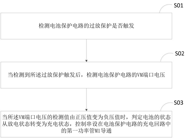
[0042] In the first embodiment, if figure 2 As shown, a power tube control method for a battery protection circuit is provided, including the following steps:
[0043] S01: Detect whether the over-discharge protection of the battery protection circuit is triggered.
[0044] In this step, the following steps are used to detect whether the over-discharge protection of the battery protection circuit is triggered:
[0045] S011: Detect the terminal volt...
PUM
 Abstract
Description
Claims
Application Information