A charging system and method

A technology of a charging system and a charging method, which is applied in the direction of current collectors, electric vehicles, electrical components, etc., can solve problems such as limiting fast charging capabilities, heating of mobile devices, and large pressure differences, so as to avoid cable and connector compatibility, High voltage, low current, high efficiency and fast, avoiding severe heating effect

Active Publication Date: 2018-12-18
BLACKSHARK TECH NANCHANG CO LTD
View PDF5 Cites 0 Cited by
  • Summary
  • Abstract
  • Description
  • Claims
  • Application Information

AI Technical Summary

Problems solved by technology

[0004] The defect of the prior art scheme 1: Since the input voltage of the battery charger in this scheme is relatively high, and the voltage difference between the output voltage (such as 4.4V) is relatively large, the topology of the common buck-boost control circuit (BUCK or BUCK-BOOST) is adopted. The conversion efficiency of the charger is low (measured <90%), which leads to serious heating of the mobile device during charging, which limits the fast charging capability
[0006] Defects of the existing technical solution 2: 1. The current of the cable connected between the charger and the mobile device exceeds the specification of ordinary cables, and special customized cables and connecting sockets are required; 2. There is an electrical overstress (EOS) in the direct charging circuit potential risks

Method used


Image

  • A charging system and method
  • A charging system and method
  • A charging system and method

Examples


Embodiment 1

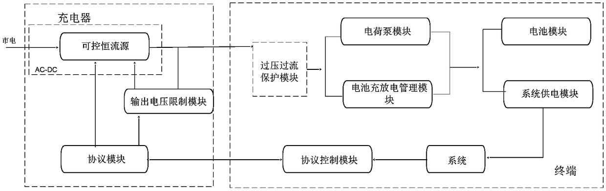
[0076] Such as figure 2 As shown in the schematic structural diagram of the charging system of the present invention, in addition to the modules, functions and connection relationships that have been described above, the terminal side also includes an overvoltage and overcurrent protection module, and the overvoltage and overcurrent protection module is located in the charging system. Between the device and the charge pump module of the terminal, the overvoltage and overcurrent protection module is an external module located in the terminal. The battery charging and discharging management module includes an overvoltage and overcurrent protection module, which is used to detect the voltage and current delivered to the terminal by the charger and provide an overvoltage and overcurrent shutdown protection function, and limit the input current to a safe zone. The path management module is used to dynamically allocate the charging current path according to the charging state of t...

Embodiment 2

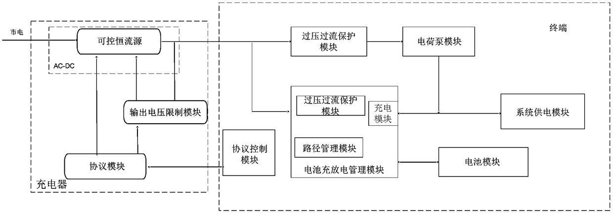
[0080] Such as image 3 As shown, it is a schematic structural diagram of another battery charging system of the present invention, and the same parts as those in Embodiment 1 will not be repeated here. The difference between this embodiment and Embodiment 1 is that instead of using an external overvoltage and overcurrent protection module, the overvoltage and overcurrent protection module in the battery charge and discharge management module is directly used to perform overvoltage and overcurrent protection. Protect. Specifically, the charger is electrically connected to the overvoltage and overcurrent protection module in the battery charge and discharge management module, and the output terminal of the overvoltage and overcurrent protection module is electrically connected to the input terminal of the charge pump module , the output end of the charge pump module is electrically connected to the battery charge and discharge management module and the system power supply modu...

Embodiment 3

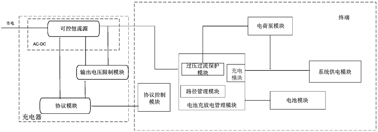
[0083] Such as Figure 4As shown, a schematic structural diagram of another battery charging system of the present invention is the same as the first half of the structure of the charging system described in Embodiment 1, and will not be repeated here. The difference is also obvious. In this embodiment, the system power supply module is connected in series to the rear side of the battery charge and discharge management module, so the path management module in the battery charge and discharge management module is not needed in the constant current charging stage. function, but the pre-charging and constant voltage charging stages still need path management. Here, it should be noted that the component modules in the drawings of the present invention are mainly based on the component modules required for constant current charging, so all components of the battery charge and discharge management module are omitted in the drawings of this embodiment. The above path management modu...


PUM


Abstract

The invention provides a charging system and method. The charging system comprises a charger and a terminal; the charger comprises a controllable constant current source, an output voltage limiting module and a protocol module; the terminal comprises a charge pump module, a protocol control module, an over-voltage and over-current protection module, a battery module, a battery charge and discharge management module and system power supply module; the controllable constant current source and the output voltage limiting module of the charger are electrically connected with the over-voltage and over-current protection module of the terminal, and the over-voltage and over-current protection module is electrically connected with the charge pump module, the battery charge and discharge management module, the battery module and the system power supply module. According to the charging system and method provided by the invention, high-voltage small-current efficient and quick charge is realized by different combination and connection manners of the battery charger and the charge pump module. The compatibility problem of a cable and a connector in the current large-current quick charge scheme, and the serious heating problem of mobile equipment in the current high-voltage quick charge scheme is also avoided.

Description

technical field [0001] Embodiments of the present invention relate to a battery charging solution, and in particular to a charging system and method. Background technique [0002] In today's era of rapid technological development, mobile terminals have become an indispensable part of people's daily life, but the slow charging of mobile terminals and poor battery life have always been problems that people want to overcome. Now there are two traditional fast charging solutions: : [0003] Existing solution 1: In order to ensure fast charging, the charging power is increased by increasing the charging voltage, and the buck-boost control circuit (BUCK or BUCK-BOOST) is used inside the mobile device as a battery charger to charge the battery; [0004] The defect of the prior art scheme 1: Since the input voltage of the battery charger in this scheme is relatively high, and the voltage difference between the output voltage (such as 4.4V) is relatively large, the topology of the c...

Claims


Application Information

Patent Timeline
Patent Type & Authority Patents(China)
IPC IPC(8): H02J7/00
CPCH01M10/4257H02J7/00H02J7/0029H02J7/00304Y02B40/00Y02E60/10
Inventor 钟光华唐志勇
Owner BLACKSHARK TECH NANCHANG CO LTD
Why Eureka
Try Eureka