Emergency electric shock rescue device for substation

A substation, emergency technology, applied in lighting devices, lighting devices, lighting device parts and other directions, to achieve the effect of simple operation, easy to store and carry

Inactive Publication Date: 2022-02-18
郭旸 +1
View PDF0 Cites 0 Cited by
  • Summary
  • Abstract
  • Description
  • Claims
  • Application Information

AI Technical Summary

Problems solved by technology

[0009] The purpose of the present invention is to provide an emergency electric shock rescue device used in substations to solve the problems that rescuers often encounter when carrying wooden sticks to the scene of electric shock proposed in the above background technology

Method used


Image

  • Emergency electric shock rescue device for substation
  • Emergency electric shock rescue device for substation
  • Emergency electric shock rescue device for substation

Examples


Embodiment 1

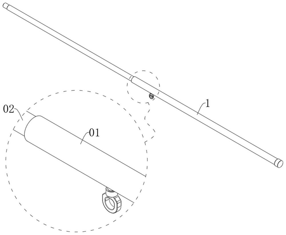
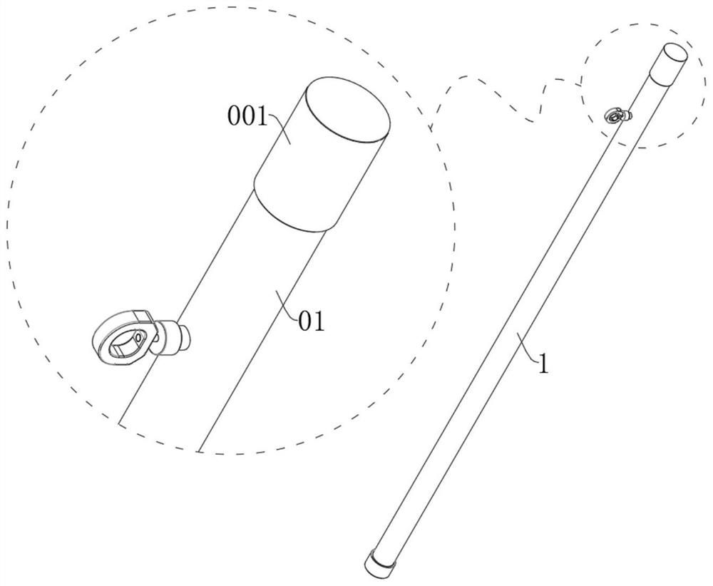
[0083] see figure 1 and figure 2 , the present invention provides a technical solution for an emergency electric shock rescue device used in a power substation, which includes a telescopic rod 1 capable of changing its length by stretching and stretching, and a dust jacket 001 set on the head end of the telescopic rod 1 for dustproofing. The telescoping rod 1 includes a grip rod 01 that is held by human hands during use and a driving rod 02 that can be accommodated inside the grip rod 01 . The dustproof cover 001 is a sleeve with one end open, and the dustproof cover 001 is made of insulating silica gel.

[0084] During daily placement, the tail end of the grip 01 can be turned downward, the lever 02 can be put into the interior of the grip 01, and then the dust cover 001 can be tightly placed on the head of the grip 01. At this time, the telescopic rod 1 is in the storage state, and under the protection of the dustproof cover 001 , external water and dust cannot enter the ...

Embodiment 2

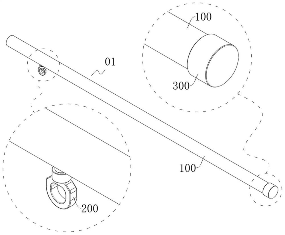
[0089] see image 3 , in the technical solution provided by the present invention, the grip bar 01 includes a grip bar shaft 100 for holding, a set of self-locking components 200 for preventing the shift lever 02 from shrinking, and a set for preventing the shift lever 02 from falling. Falling rod holder 300.

[0090] see Figure 4-Figure 6 , In the technical solution provided by the present invention, the grip shaft 100 includes a straight cylindrical rod body 110 with open left and right ends and a straight cylindrical lock cylinder 120 with open upper and lower ends. The top cylinder body of the lock cylinder 120 is integrally connected with the bottom pipe body at the left end of the rod body 110, and the cylinder cavity of the lock cylinder 120 communicates with the lumen of the rod body 110, and the driving rod 02 is inserted from the tail end of the rod body 110. In the lumen of the first rod body 110 .

[0091] The outer wall of the tube at the tail end of the first...

Embodiment 3

[0108] see Figure 10 , in the technical solution provided by the present invention, the lever 02 includes a lever body 400 for picking up electric wires, a lever head 500 for auxiliary lighting and a lever head 500 for The lever tail 600 of power supply.

[0109] see Figure 11 , in the technical solution provided by the present invention, the lever shaft 400 includes a rod body 2 410 in the shape of a round straight tube with openings at the left and right ends, a threaded tube 1 420 in the shape of a round straight tube with openings at the left and right ends, and three grains Spherical guide beads 430 for reducing friction. The right end of the first threaded tube 420 is integrally connected with the left end of the second rod 410 , and the lumen of the first threaded tube 420 communicates with the lumen of the second rod 410 .

[0110] The lumen wall at the tail end of the rod body 2 410 is surrounded by threads for threaded fit, and the threads are used for threadedl...


PUM


Abstract

The invention discloses an emergency electric shock rescue device for a substation in the technical field of electric shock rescue equipment. The emergency electric shock rescue device comprises a telescopic rod which can stretch out and draw back to change the length of a rod body and comprises a holding rod and a shifting rod; the holding rod comprises a holding rod body, a self-locking assembly and a holding rod base, wherein the holding rod body has a storage function and can be held by a person, the self-locking assembly is installed on a pipe body at the head end of the holding rod body and used for preventing the shifting rod from contracting, and the holding rod base is screwed to a pipe opening at the tail end of the holding rod body and used for preventing the shifting rod from falling off and conducting automatic power-on and power-off control on the shifting rod. The shifting rod comprises a shifting rod body used for driving and picking the electric wire, a shifting rod head installed at the head end of the shifting rod body and used for assisting illumination, and a shifting rod tail installed at the tail end of the shifting rod body and used for being matched with the holding rod base to supply power to the shifting rod head. The emergency electric shock rescue device is convenient to store and carry in a storage state, the telescopic rod can be adjusted to be in a stretching state by swinging the holding rod in the using process, and operation is easy.

Description

technical field [0001] The invention relates to the technical field of electric shock rescue equipment, in particular to an emergency electric shock rescue device used in a substation. Background technique [0002] The common causes of accidents in substations are failures of power supply and distribution facilities, improper operation by operators, and power outages in external power grids due to bad weather. Wherein, when a person is found to be electrocuted, the finder usually looks for insulating objects such as wooden sticks nearby to push the electric wire away from the electrocuted person, so that the electrocuted wire is far away from the electrocuted person, and carries out emergency rescue measures to the electrocuted person on the spot. [0003] In the actual scene, there are many power towers, power racks, transformers, transmission lines and other equipment in the substation, and the layout is more diverse. Some places are more spacious, some places are narrower...

Claims


Application Information

Patent Timeline
Patent Type & Authority Applications(China)
IPC IPC(8): A62B35/00F21V33/00F21Y115/10
CPCA62B35/00F21V33/0064F21Y2115/10
Inventor 郭旸陈明珠周玉文
Owner 郭旸
Why Eureka
Try Eureka