
Cable trench inspection robot

A technology for patrolling robots and cable trenches, applied to manipulators, manufacturing tools, etc., can solve problems such as complicated operations, heavy physical labor, and potential safety hazards, and achieve action reliability and stability guarantees, avoid use problems, and reduce assembly volume Reduced effect

Active Publication Date: 2022-02-18
HEFEI CAS LANRUI TECH CO LTD
View PDF9 Cites 0 Cited by
  • Summary
  • Abstract
  • Description
  • Claims
  • Application Information

AI Technical Summary

Problems solved by technology

However, the disadvantages of thermal wires are: firstly, the cables located on both sides of the cable tunnel are bundled and arranged in bundles, and the thermal wires can only monitor the high temperature changes of the adjacent cables that are close to each other, and the thermal wires located at the farthest end The temperature change monitoring effect of the cable is very poor
The existence of the firewall makes it necessary to repeatedly take out the tunnel inspection robot from the previous tunnel unit-reset the cover plate on the previous tunnel unit-remove the cover plate of the new tunnel unit-replace the tunnel inspection robot every time it inspects the tunnel inspection robot. The process of entering the tunnel inspection robot is extremely complicated and requires a lot of physical labor, which obviously seriously restricts the actual inspection efficiency.
On the other hand, as stated above, the cables in the cable tunnel are arranged in bundles, so there is a certain height. The traditional tunnel inspection robot can inspect the height constant, and there must be some dead ends of the cables that cannot be inspected, resulting in inspection loopholes. ,There are security risks

Method used


Image

  • Cable trench inspection robot
  • Cable trench inspection robot
  • Cable trench inspection robot

Examples


Embodiment Construction

[0052] In order to facilitate the overall understanding, the structure and working method of the specific embodiment of the entire cable trench inspection robot are described as follows:

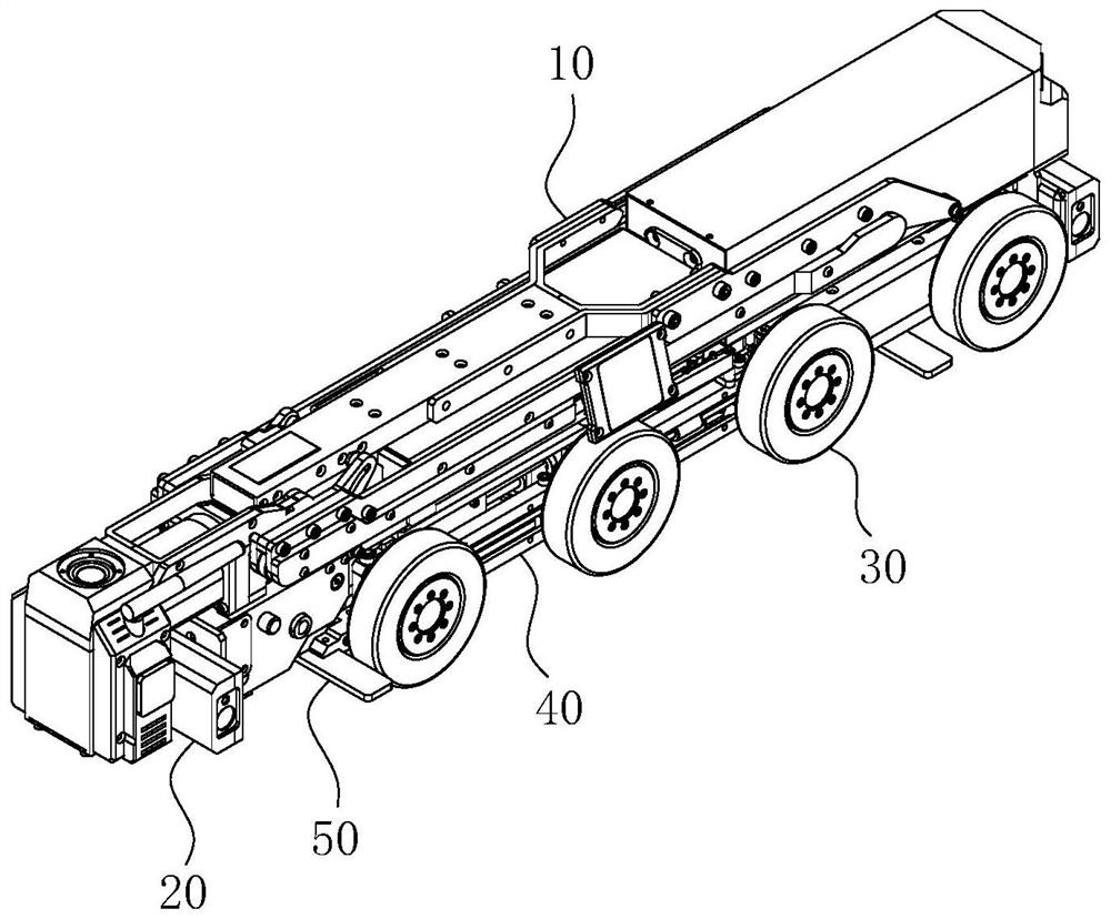
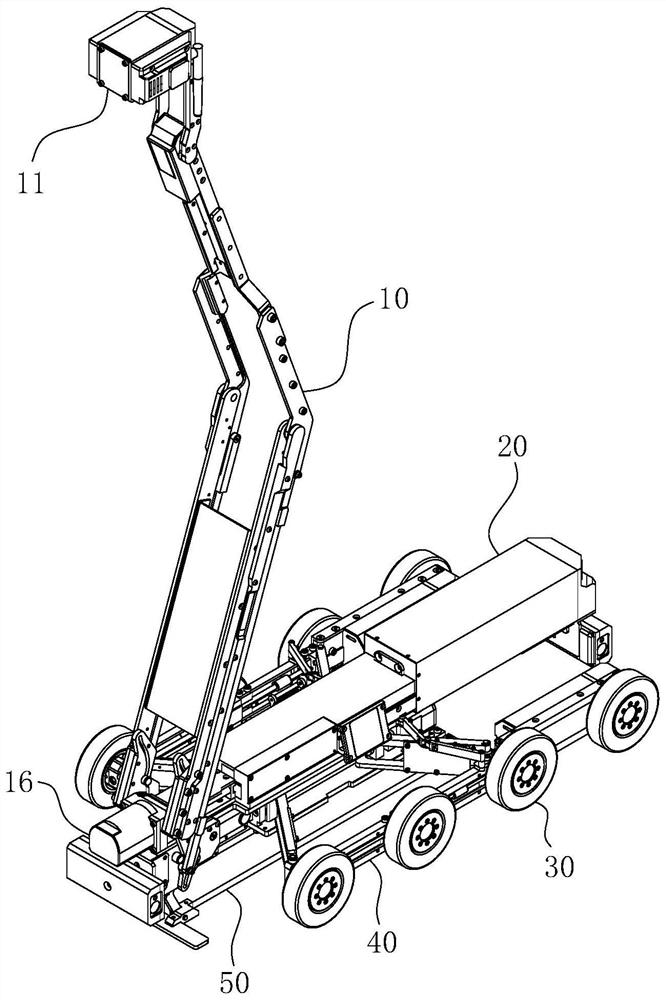
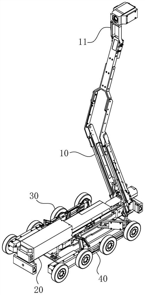
[0053] Cable trench inspection robot, also namely the present invention, such as Figure 1-13 As shown, its main body includes a car body 20 , an unfolding system 40 for deploying the running part, a jacking system 50 for jacking up the complete machine, and a workpiece lifting platform 10 as a functional part arranged on the car body 20 . in:

[0054] 1. Deployment system 40

[0055] Deployment system 40, such as Figure 1-3 And shown in 9-11, comprise a group of bottom plate 41 that is arranged on the car body 20 below, a group of power motors namely power source 42, a group of power screw mandrel 45, two groups of moving blocks 43 and four groups of cantilever plates 44. During actual assembly, the bottom plate 41 is rectangular in shape and is horizontally arranged at the bottom of th...


PUM


Abstract

The invention belongs to the technical field of cable inspection, and particularly relates to a cable trench inspection robot. The cable trench inspection robot comprises a vehicle body and a workpiece lifting platform installed on the vehicle body. The workpiece lifting platform comprises a working unit and a four-connecting-rod assembly used for jacking the working unit. A lower guide groove is formed in a short connecting rod at the head end of the four-connecting-rod assembly, an upper guide groove is formed in a long connecting rod at the upper part, and the upper guide groove and the lower guide groove are matched to form a splayed guide part with an opening facing a short connecting rod at the tail end; the working end of a straight stroke driving source horizontally extends towards the two sets of guide grooves to form guide blocks, and therefore the guide blocks, the upper guide groove and the lower guide groove form a guide rail sliding block matching relation at the same time. According to the cable trench inspection robot, through-wall operation can be achieved through the cable trench, so that many use problems caused by the existence of a firewall are avoided, and a predetermined inspection task can be completed efficiently.

Description

technical field [0001] The invention belongs to the technical field of cable inspection, and in particular relates to a cable trench inspection robot. Background technique [0002] The occurrence of fires in cable tunnels is a process of gradual accumulation. With the increase of time, due to the aging of the insulation layer, the accumulation of dust and oil, and the looseness of the intermediate joints, the local temperature of the cable will gradually rise, which will cause a fire. Before the accident occurs, if the temperature and smoke inside the cable tunnel can be effectively monitored in real time, the fire can be prevented before it happens. Although the monitoring problem of cable tunnel has attracted people's attention, but has not found a proper and reasonable solution. [0003] Traditional cable tunnels are manually inspected. At regular intervals, inspectors enter the tunnel and use temperature measuring instruments to manually check the temperature of the i...

Claims


Application Information

Patent Timeline
IPC IPC(8): B25J11/00B25J5/00B25J19/00B25J19/02
CPCB25J11/00B25J5/007B25J19/00B25J19/023
Inventor 孙丙宇孙璞姚德亮郭兴源
Owner HEFEI CAS LANRUI TECH CO LTD
Learn More