
Computer-implemented method and system for designing a workcell layout

a technology of workcell and computer, applied in computing, instruments, data processing applications, etc., can solve the problems of only performing layout design, layout design typically has to be completely recalculated, and is cumbersome and time-consuming, so as to reduce inefficiencies and facilitate use. , the effect of flexibility

Inactive Publication Date: 2006-08-15
FORD MOTOR CO
View PDF5 Cites 3 Cited by
  • Summary
  • Abstract
  • Description
  • Claims
  • Application Information

AI Technical Summary

Benefits of technology

[0013]Another advantage of the present invention is its flexibility and ease of use. This advantage allows users, such as workcell operators, to utilize the present invention with minimal or no prior training. Enabling operators themselves to utilize the present invention also takes advantage of the operators' practical knowledge and experience.
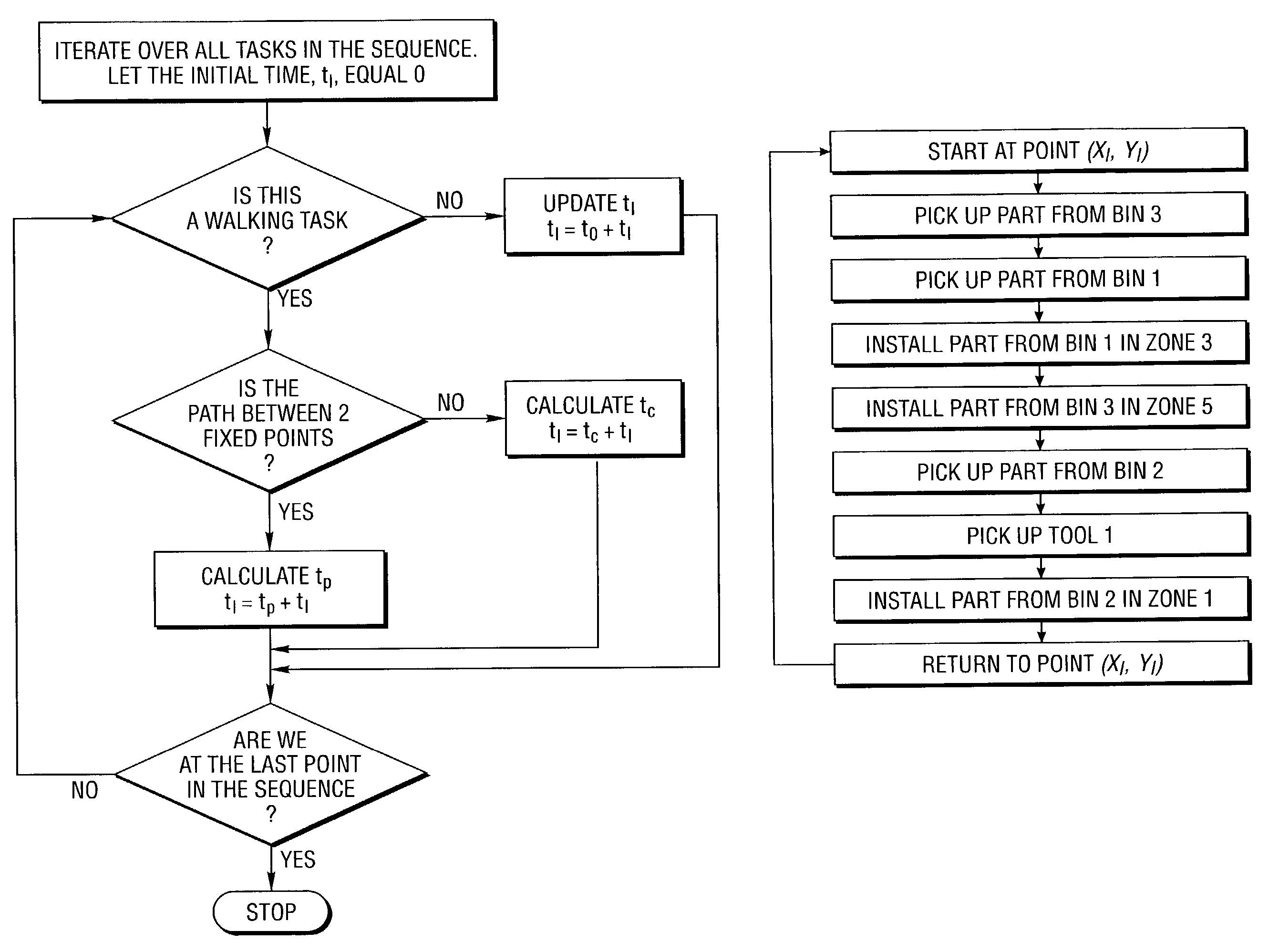
[0014]One embodiment of the present invention allows for real-time scenario planning by providing instantaneous calculations of the total time required to perform the tasks assigned to that workcell and of the total walking time. This feature allows the user to quickly evaluate a large variety of possibilities, a process that is very difficult using prior art methods.
[0015]Aspects of the present invention may be implemented on a web-based or other network platform so that aspects of the invention are not tied to any specific piece of hardware, and as a result, may be universally accessible.
[0016]Changes made by a user may be stored in a central database so that updated information is not lost. This feature allows for propagation of best part allocations and of optimal walking paths from worker to worker.
[0017]Another aspect of the present invention supports simulation of the operator walk through a VRML interface. This feature allows users to see how their work plans affect neighboring operator workcells.
[0018]The present invention may provide advice on walk path optimization with respect to given layout / process constraints by using a host of mathematical optimization methods well known to those versed in the art. This feature greatly cuts down the inefficiencies arising from prior art methods and practices.

Problems solved by technology

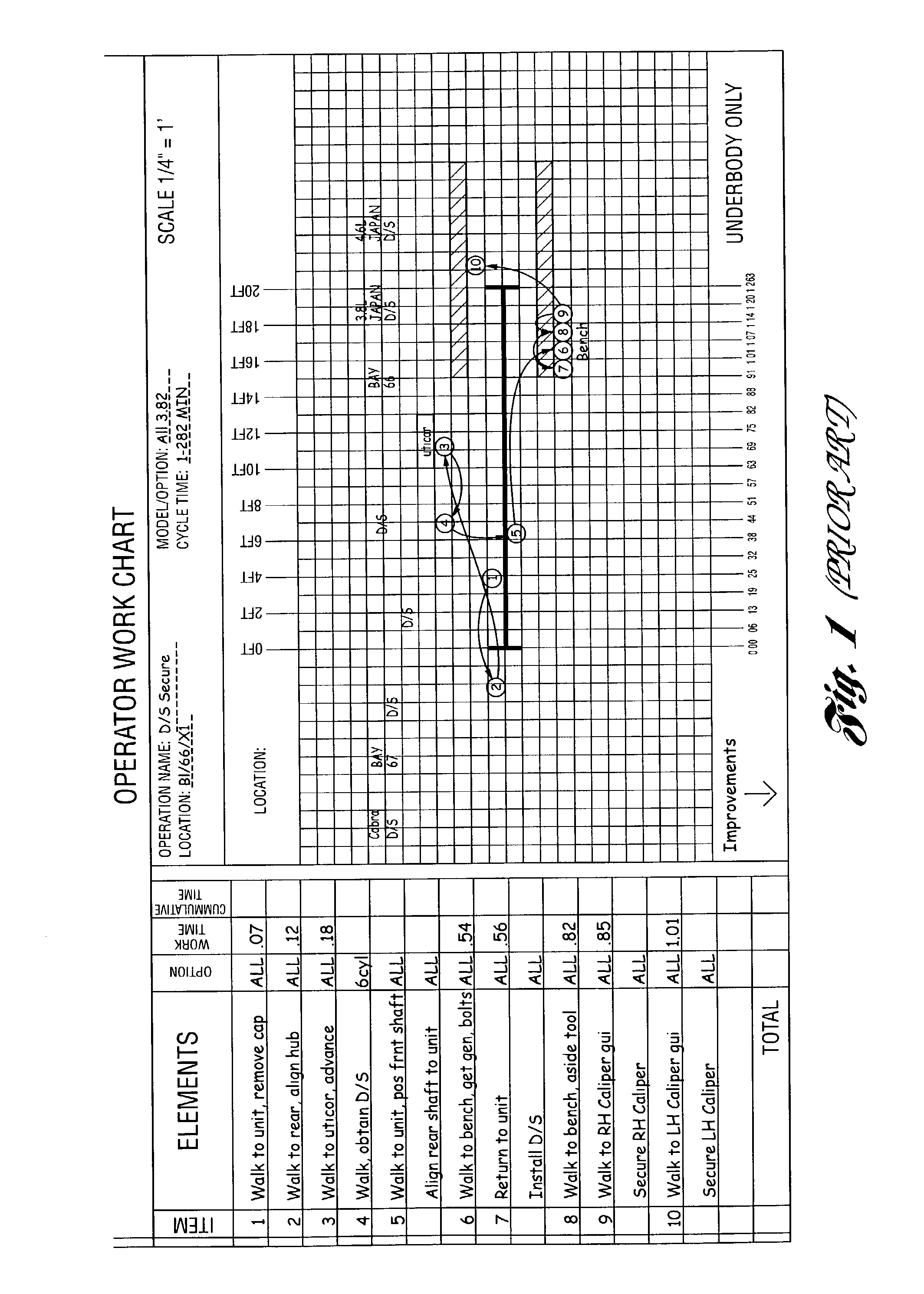
Currently, workcell layout design is a cumbersome and time-consuming process.
One disadvantage of this methodology is that every time a change is made in the sequence of workcell tasks, or any of the workcell contents are moved, the layout design typically has to be redone from scratch and completely recalculated.
Another disadvantage of the conventional methodology is that it is typically only performed by a small group of plant engineers who are responsible for optimizing the efficiency of potentially hundreds of individual workcells and operators.
This method is particularly inefficient because the operators themselves often know best what workcell layout(s) may increase the efficiency of their work and, consequently, the quality of the products.
However, these tools do not directly address the problem of increasing the efficiency of a workcell layout, vis-a-vis, the moving vehicles being assembled.
As a whole, the situation and methods outlined above do not satisfactorily address the problem of workcell design and planning in a moving assembly line for at least three reasons.
First, when performed in this way, the planning process is cumbersome and time consuming.
Second, the tools that have been used until now are static and suitable only for engineering planning: they do not support real-time line operator interaction.
Third, since the process is largely manual, it is not easy for industrial engineers to uncover the layout that will produce the shortest operator walking path.
In other words, inefficient choices (e.g., choices forcing the operator to needlessly spend time walking) may be made.
In this regard, there are many factors that may complicate the choice of the best arrangement.
In spite of research in the area of moving assembly line design and of line balancing, the practical application of published algorithms is limited.
First, the published algorithms are not sufficiently flexible to model the actual conditions of assembly line workstations.
Second, accurate data is difficult to obtain and maintain: often, there is no current record of a workcell layout; that is, when a workcell layout is modified the corresponding central records are not updated.
This manual approach can be very tedious because of the large amount of manual calculations required for each path and workcell.
It is not surprising that this method often fails to produce an efficient workcell arrangement.
The fact that the method is used for each workcell in the assembly line compounds time inefficiencies.
While this approach represents an improvement over the paper and pencil method, there is no attempt to compute on the fly walking time based on the layout of the workcell, nor is there any attempt to systematically optimize workcell configuration.

Method used


Image

  • Computer-implemented method and system for designing a workcell layout
  • Computer-implemented method and system for designing a workcell layout
  • Computer-implemented method and system for designing a workcell layout

Examples


Embodiment Construction

[0030]The following detailed description of preferred embodiments of the present invention is described and illustrated in the context of the automotive industry. Those involved in the field of manufacturing and product assembly will recognize, however, that the innovative concepts associated with this invention may be applied to virtually any type of manufacturing or assembly.

MODAPTS

[0031]The concept of normal time is the time a qualified, experienced operator (approximately 5′-7″ 145 pounds) would work at a comfortable pace, which can be maintained all day without undue stress. This is often called an “air day's work” Modular Arrangement of Predetermined Time Standards (MODAPTS) is based upon this principle. See, International MODAPTS Assoc. (1990) copyrights, Kalamazoo, Mich. and Minter, A. L. (1983) MODAPTS; Management Services, MODAPTS may be used in assembly plants in place of the old-fashioned “stopwatch study”, which was a subjective way of determining on operator's efficien...


PUM


Abstract

Preferred embodiments include receiving input defining dimensions for a workcell and a size and location for one or more objects within the workcell, receiving input defining a walking velocity for an operator within the workcell and one or more tasks to be completed during a workcell cycle, receiving input defining one or more times and locations to complete the one or more tasks within the workcell, calculating a total walking time to complete the one or more tasks during the workcell cycle based upon the size and location of the object(s), the time(s) and location(s) to complete the task(s) and the operator walking velocity, and outputting the total walking time for the workcell cycle and a graphical representation of the workcell including the object(s) and an operator walking path between points within the workcell at which the one or more tasks are completed.

Description

BACKGROUND OF THE INVENTION[0001]1. Field of the Invention[0002]The present invention relates to a computer-implemented method and system for designing a workcell layout.[0003]2. Background Art[0004]Currently, workcell layout design is a cumbersome and time-consuming process. It is either performed manually with paper and pencil or with a non-interactive, two-dimensional computer interface. One disadvantage of this methodology is that every time a change is made in the sequence of workcell tasks, or any of the workcell contents are moved, the layout design typically has to be redone from scratch and completely recalculated. Another disadvantage of the conventional methodology is that it is typically only performed by a small group of plant engineers who are responsible for optimizing the efficiency of potentially hundreds of individual workcells and operators. This method is particularly inefficient because the operators themselves often know best what workcell layout(s) may increas...

Claims


Application Information

Patent Timeline
Patent Type & Authority Patents(United States)
IPC IPC(8): G06F17/50G06Q10/06
CPCG06Q10/06G06F17/50G06F30/00G06Q10/0639
Inventor GUSIKHIN, OLEG YURIEVITCHKLAMPFL, ERICAROSSI, GIUSEPPECOFFMAN, JR., PAUL EUGENEAGUWA, CELESTINE CHUKWUEMEKAMARTINAK, TERRENCE
Owner FORD MOTOR CO
Learn More