Check patentability & draft patents in minutes with Patsnap Eureka AI!

Battery fault detection device and method

A battery fault detection and battery technology, applied in the direction of measuring devices, measuring electricity, measuring electrical variables, etc., can solve the problems of battery explosion life, the inability to obtain accurate open circuit voltage of the battery, and no accurate and effective battery fault detection method

Pending Publication Date: 2022-02-18
TEAM YOUNG TECH CO LTD
View PDF0 Cites 1 Cited by
  • Summary
  • Abstract
  • Description
  • Claims
  • Application Information

AI Technical Summary

Problems solved by technology

[0002] In the current prior art, if one of the batteries fails when using a multi-cell battery pack, the multi-cell battery pack must stop working entirely, otherwise it may cause battery explosion or shorten the service life.
Although there may be different battery fault detection methods today, there are two problems. First, even if the multi-cell battery packs on the market know that there is a battery fault, the battery pack can only choose to stop power supply, and cannot effectively eliminate it at the same time. The fault also maintains the stable power supply of the back-end system. Second, there is actually no accurate and effective battery fault detection method on the market. This is because the batteries on the market cannot obtain accurate open circuit voltage (OCV or offline voltage). The open circuit voltage must be measured after offline or before starting, so that the accurate internal resistance of the battery cannot be effectively obtained during the use of multiple batteries. Generally, the battery is modeled by resistance and voltage (open circuit or conduction voltage). Battery failure behavior; therefore, how to detect battery failure more effectively needs to be solved urgently

Method used


Image

  • Battery fault detection device and method
  • Battery fault detection device and method
  • Battery fault detection device and method

Examples


Embodiment Construction

[0021] In the following, the components, steps and effects of the battery fault detection device and method of the present invention will be described by listing corresponding preferred embodiments in conjunction with the accompanying drawings. However, the components and dimensions of the battery fault detection device and method in each accompanying drawing The appearance and appearance are only used to illustrate the technical characteristics of the present invention, but not to limit the present invention.

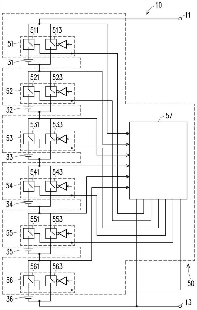
[0022] refer to figure 1 An embodiment is shown, and the figure is a block diagram of the charging / discharging system 10 with M batteries in the present invention. In this embodiment, M is 6. The charging / discharging system 10 with M batteries in the present invention is applied to an electric power The power system can be a variety of devices that need to be powered by batteries, such as portable computers, mobile phones, electric vehicles, electric locomotives, and p...


PUM


Abstract

The invention provides a battery fault detection device and method. The device comprises a control unit which is used for detecting the open-circuit voltage, the break-over voltage and the break-over current of a battery, wherein the break-over voltage and the break-over current are outputted for a preset number N times, and N is greater than 1; the control unit calculates the nth break-over voltage of the battery, the open-circuit voltage closest to the nth break-over voltage in the detection time and the nth break-over current of the battery to obtain the nth internal resistance value of the battery, and n is a positive integer and n is equal to 1 to N; when n is greater than or equal to 2, an absolute difference value between the (n-1) th internal resistance value and the nth internal resistance value of the battery is calculated, and a result obtained by dividing the absolute difference value by the (n-1) th internal resistance value is taken as the nth resistance variation of the battery; and whether the battery fails or not is judged according to the nth resistance variation of the battery.

Description

technical field [0001] The invention relates to the field of battery technology, in particular to a battery fault detection device and method. Background technique [0002] In the current prior art, if one of the batteries fails when a multi-cell battery pack is used, the multi-cell battery pack must stop working completely, otherwise the battery may explode or its lifespan may be shortened. Although there may be different battery fault detection methods today, there are two problems. First, even if the multi-cell battery packs on the market know that there is a battery fault, the battery pack can only choose to stop power supply, and cannot effectively eliminate it at the same time. The fault also maintains the stable power supply of the back-end system. Second, there is actually no accurate and effective battery fault detection method on the market. This is because the batteries on the market cannot obtain accurate open circuit voltage (OCV or offline voltage). The open c...

Claims


Application Information

Patent Timeline
IPC IPC(8): G01R31/389G01R31/396G01R31/385
CPCG01R31/389G01R31/396G01R31/385
Inventor 林子闵
Owner TEAM YOUNG TECH CO LTD
Features
  • R&D
  • Intellectual Property
  • Life Sciences
  • Materials
  • Tech Scout
  • Unparalleled Data Quality
  • Higher Quality Content
  • 60% Fewer Hallucinations
Learn More