Intelligent building fire-fighting monitoring equipment

A fire monitoring and intelligent building technology, applied in mechanical equipment, mechanical audible signals, televisions, etc., can solve the problems of poor application efficiency and low practical value, and achieve the effects of easy cleaning, convenient listening and positioning, and simple operation

Active Publication Date: 2022-02-22
成都方烨科技有限公司
View PDF4 Cites 3 Cited by
  • Summary
  • Abstract
  • Description
  • Claims
  • Application Information

AI Technical Summary

Problems solved by technology

[0004] The purpose of the present invention is to solve the shortcomings of the existing fire monitoring equipment in use, most of which are fixed-angle shoot

Method used


Image

  • Intelligent building fire-fighting monitoring equipment
  • Intelligent building fire-fighting monitoring equipment
  • Intelligent building fire-fighting monitoring equipment

Examples


Embodiment 1

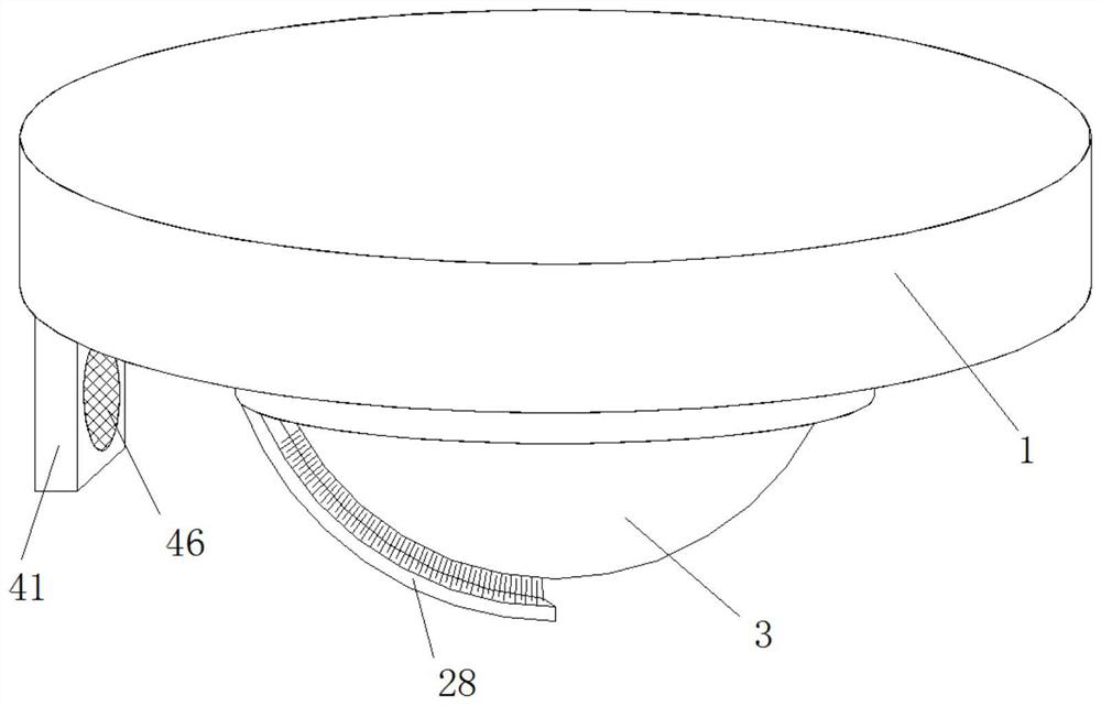
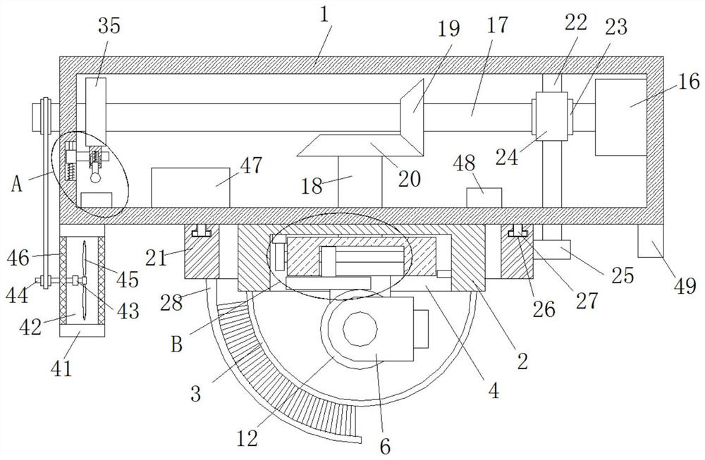
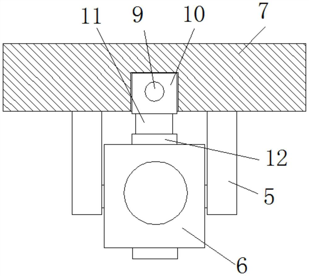
[0028] refer to Figure 1-8 , an intelligent building fire monitoring device, comprising a housing 1, a base 2 is fixedly installed on the bottom of the housing 1, a glass cover 3 is installed on the bottom of the base 2, a placement groove 4 is opened on the bottom of the base 2, and the top of the placement groove 4 The inner wall is rotatably connected with a base plate 7, and the bottom of the base plate 7 is fixedly equipped with two symmetrically arranged fixed plates 5, and a camera 6 is rotatably connected between the two fixed plates 5, and the base plate 7 is provided with a lateral angle adjustment mechanism. A vertical angle adjustment mechanism is provided, and the vertical angle adjustment mechanism is connected to the camera 6 through transmission. The bottom of the housing 1 is connected to a gear ring 21 in rotation. The gear ring 21 is provided with a cleaning mechanism. The cleaning mechanism cooperates with the glass cover 3. A motor 16 is fixedly installed...

Embodiment 2

[0035] refer to Figure 1-8 , an intelligent building fire monitoring device, comprising a housing 1, a base 2 is fixedly installed on the bottom of the housing 1, a glass cover 3 is installed on the bottom of the base 2, a placement groove 4 is opened on the bottom of the base 2, and the top of the placement groove 4 The inner wall is rotatably connected with a base plate 7, and the bottom of the base plate 7 is fixedly equipped with two symmetrically arranged fixed plates 5, and a camera 6 is rotatably connected between the two fixed plates 5, and the base plate 7 is provided with a lateral angle adjustment mechanism. A vertical angle adjustment mechanism is provided, and the vertical angle adjustment mechanism is in transmission connection with the camera 6. The bottom of the housing 1 is rotatably connected to a gear ring 21, and a cleaning mechanism is provided on the gear ring 21. The cleaning mechanism cooperates with the glass cover 3, and the housing A motor 16 is fix...


PUM


Abstract

The invention belongs to the technical field of monitoring equipment, particularly relates to intelligent building fire-fighting monitoring equipment, and aims to solve the problems that existing fire-fighting monitoring equipment is mostly subjected to fixed-angle shooting monitoring in use, is low in practical value and is poor in application efficiency in case of fire disasters. According to the provided scheme, the intelligent building fire-fighting monitoring equipment comprises a shell, a base is fixedly installed at the bottom of the shell, a glass cover is installed at the bottom of the base, a containing groove is formed in the bottom of the base, a bottom plate is rotationally connected to the inner wall of the top of the containing groove, two symmetrically-arranged fixing plates are fixedly installed at the bottom of the bottom plate, a camera is rotationally connected between the two fixing plates, a transverse angle adjusting mechanism is arranged on the bottom plate, and a vertical angle adjusting mechanism is arranged on the bottom plate. According to the invention, the operation is simple, the use is convenient, multi-angle adjustment can be conveniently carried out on the camera, the camera can be conveniently cleaned, people can listen to sound and position in smoke conveniently, and the use by people is facilitated.

Description

technical field [0001] The invention relates to the technical field of monitoring equipment, in particular to an intelligent building fire monitoring equipment. Background technique [0002] With the continuous development of various buildings, the scale of the building is getting larger and higher, the level of the building is getting higher and higher, and the standard of the building is getting higher and higher. Features, automatic fire alarm and monitoring of personnel entering and leaving have become an indispensable and important part of high-rise buildings. [0003] Most of the existing fire monitoring equipment in use is fixed-angle shooting monitoring, which has low practical value and poor application efficiency in case of fire. Therefore, we propose an intelligent building fire monitoring equipment. Contents of the invention [0004] The purpose of the present invention is to solve the shortcomings of the existing fire monitoring equipment in use, most of whic...

Claims


Application Information

Patent Timeline
IPC IPC(8): G08B17/10G08B3/02H04N7/18H04N5/232B08B1/00B08B1/04F16M11/12
CPCG08B17/10G08B3/02H04N7/18B08B1/002B08B1/04F16M11/123F16M11/12H04N23/695Y02E10/50
Inventor 陈建鸿
Owner 成都方烨科技有限公司
Why Eureka
Try Eureka