
Expanding and supporting device for thermal insulation pipe

The technology of a bracing device and an insulating pipe is applied in the field of expanding bracing devices for thermal insulating pipes, which can solve the problems of poor sealing effect of pipelines, low efficiency, and unfavorable connection of two thermal insulating pipes, and achieves the effect of improving the buckle angle.

Pending Publication Date: 2022-02-25
天津华湘科技有限公司
View PDF0 Cites 0 Cited by
  • Summary
  • Abstract
  • Description
  • Claims
  • Application Information

AI Technical Summary

Problems solved by technology

[0002] At present, during the use of the existing heat preservation pipes, it is not convenient to realize more convenient welding of the two heat preservation pipes. It is not convenient to expand the two insulation pipes in the subsequent protection process of the insulation pipe. During the docking installation, it is necessary to use a section of reinforcement pipe to set the two insulation pipes together. The existing method is to cut a section of reinforcement pipe and use shears Cut off the pipe wall and hug the plastic pipes at both ends, and then strengthen the connection. There are gaps, and the connection is not reliable. Now it is necessary to expand a section of the reinforced pipe, and then cool down to realize the tight embrace of the plastic pipe, resulting in subsequent The cutting method is not good, which is not conducive to the sealing and bridging of the insulation pipe sleeve after hot melting. The traditional bridging method is too cumbersome, and the sealing effect between the pipes is poor

Method used


Image

  • Expanding and supporting device for thermal insulation pipe
  • Expanding and supporting device for thermal insulation pipe
  • Expanding and supporting device for thermal insulation pipe

Examples


Embodiment Construction

[0022] The present invention will be further described in detail below through the specific examples, the following examples are only descriptive, not restrictive, and cannot limit the protection scope of the present invention with this.

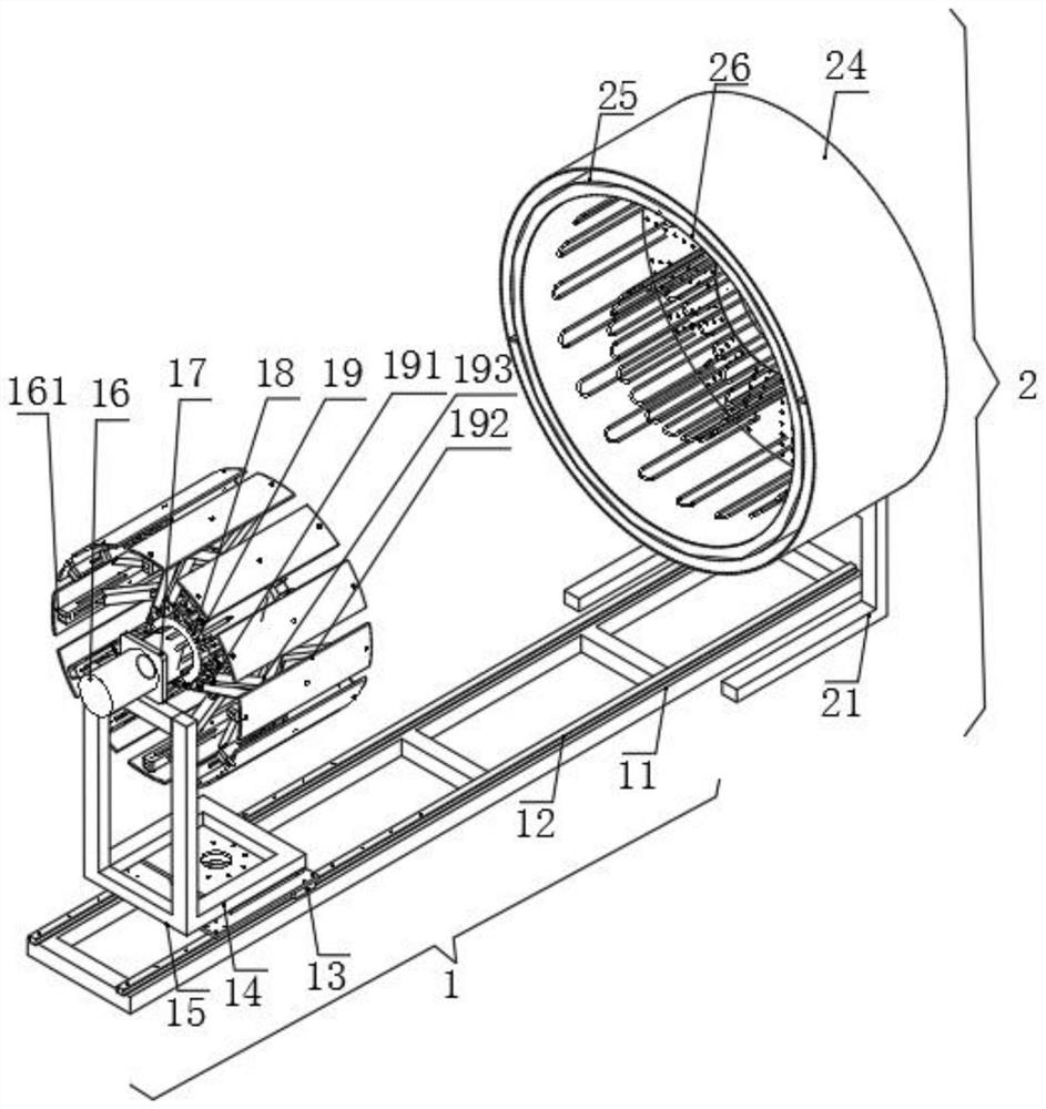
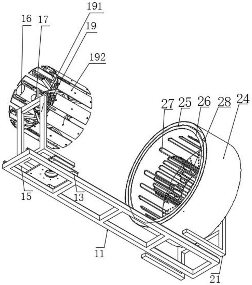
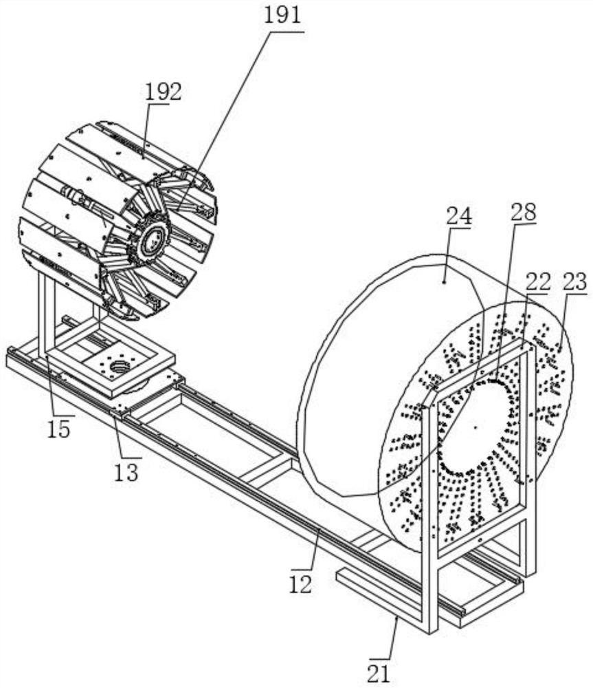
[0023] see Figure 1-4 , the present invention provides a technical solution: a thermal insulation pipe expansion device, including an expansion mechanism 1, the expansion mechanism 1 includes a first square steel pipe 11 placed on the ground support, two first square steel pipes 11 The top surface is successively provided with strip slideways 12 horizontally, and the top edges of the strip slideways 12 on both sides are horizontally equipped with sliding blocks 13, and the top surface of the sliding block 13 is integrally supported with a first square frame 14. The profile of square frame 14 is square, and is positioned at the end side wall of first square frame 14 and is vertically equipped with support frame 15, and the top middle part of...


PUM


Abstract

The invention provides an expanding and supporting device for a thermal insulation pipe. The expanding and supporting device comprises an expanding and supporting mechanism, wherein the expanding and supporting mechanism comprises first square steel pipes supported and placed on the ground, strip-shaped sliding ways are sequentially and transversely installed on the top surfaces of the two first square steel pipes, sliding blocks are transversely installed on the top edges of the strip-shaped sliding ways on the two sides, a first square frame is integrally supported on the top surface of each sliding block, the first square frames are square in appearance, and a supporting frame is vertically installed on the side wall of the end of each first square frame. According to the expanding and supporting device for the thermal insulation pipe, through the arrangement of the square steel pipes, the strip-shaped sliding ways, the sliding blocks and the square frames, a worker can conveniently support the motor arranged on the upper portion, and sliding rails, traction rods and sliding grooves on the outer side are adjusted through stretching and retracting of the motor to conduct displacement.

Description

technical field [0001] The invention belongs to the technical field of pipe body bridging, in particular to a thermal insulation pipe expansion device. Background technique [0002] At present, during the use of the existing heat preservation pipes, it is not convenient to realize more convenient welding of the two heat preservation pipes. It is not convenient to expand the two insulation pipes in the subsequent protection process of the insulation pipe. During the butt joint installation, it is necessary to use a section of reinforcement pipe to cover the two insulation pipes together. The existing method is to cut a section of reinforcement pipe and use shears. Cut off the pipe wall and hug the plastic pipes at both ends, and then strengthen the connection. There are gaps and the connection is not reliable. Now it is necessary to expand a section of the reinforced pipe, and then cool down to realize the tight hug of the plastic pipe, resulting in subsequent The cutting me...

Claims


Application Information

Patent Timeline
Patent Type & Authority Applications(China)
IPC IPC(8): B29C57/04B29C35/02
CPCB29C57/04B29C35/02
Inventor 袁名伟袁畅
Owner 天津华湘科技有限公司
Learn More