
Door lock back locking safety knob mechanism
A door lock and knob technology, applied in building locks, building structures, buildings, etc., can solve the problems of large virtual position, shaking and large gap of anti-lock safety knobs
- Summary
- Abstract
- Description
- Claims
- Application Information
AI Technical Summary
Problems solved by technology
Method used
Image

Examples
Embodiment Construction
[0030] The principles and features of the present invention are described below in conjunction with the accompanying drawings, and the examples given are only used to explain the present invention, and are not intended to limit the scope of the present invention.
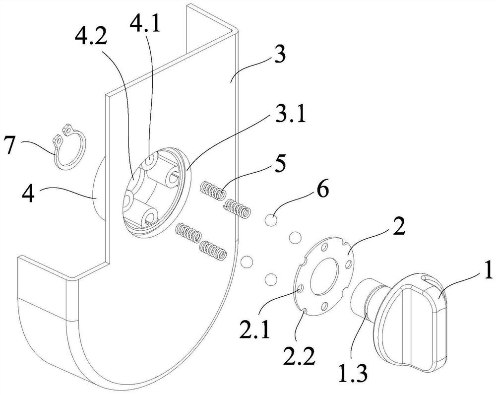
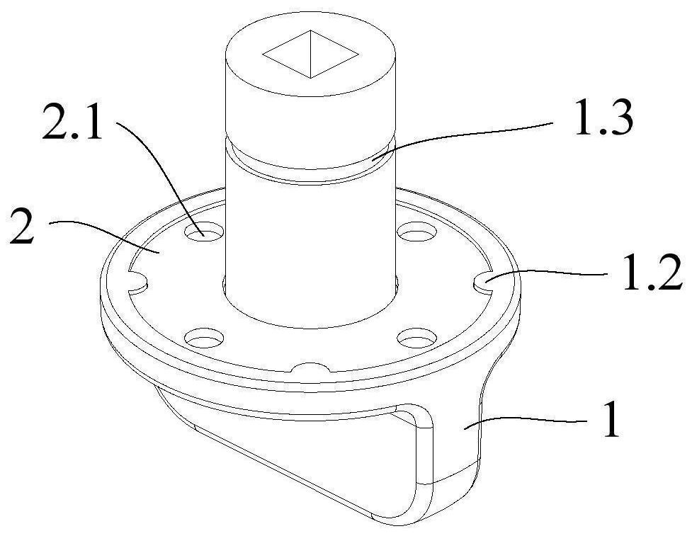
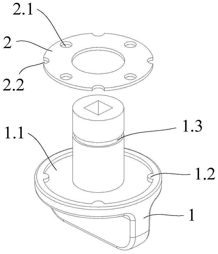
[0031] Such as Figure 1 to Figure 5 As shown, the door lock anti-lock safety knob mechanism includes a knob 1, a limit washer 2, a lock panel 3 and a tubular fixing member 4, the lock panel 3 is provided with a perforation 3.1, and the fixing member 4 is placed on the One end of the lock panel 3, the edge of the fixing member 4 is fixedly connected with the lock panel 3; the knob 1 is placed at the other end of the lock panel 3, and the rotating shaft of the knob 1 passes through the through hole 3.1 and The fixing part 4 is rotatably connected with the fixing part 4; the base body of the knob 1 extends into the through hole 3.1 and is close to the fixing part 4;
[0032] The base of the knob 1 is provided with a ...
PUM
 Abstract
Description
Claims
Application Information