
A measuring device for the transmission vibration of electric tools in the rail repair

A technology of electric tools and measuring devices, which is applied in measuring devices, vibration testing, and testing the strength of materials by applying repetitive force/pulsation force, etc. It can solve the problems of astronauts' head, palm and arm fatigue and decreased perception ability

Active Publication Date: 2022-08-09
BEIJING INST OF SPACECRAFT ENVIRONMENT ENG
View PDF0 Cites 0 Cited by
  • Summary
  • Abstract
  • Description
  • Claims
  • Application Information

AI Technical Summary

Problems solved by technology

[0002] One of the space on-orbit maintenance tasks is the on-orbit maintenance and replacement of equipment. It is necessary to remove and install the mounting screws of the fixed equipment on the orbit. This process will use a variety of special tools. This work is carried out in the space environment outside the cabin. This process will use a An electric tool for on-orbit maintenance, which is used by astronauts outside the cabin after wearing an extravehicular space suit. The tool is driven by a motor to rotate the adapter rod, and the mechanical vibration generated by the rotation of the motor and the adapter rod under microgravity is transmitted to the astronaut's gloves , and then transmitted to the palms, arms and even shoulders of the astronauts. Excessive hand-transmitted vibration may cause fatigue of the astronauts' heads, palms and arms, and decreased perception ability. To design a measurement device for hand-transmitted vibration of electric tools used in space on-orbit maintenance

Method used


Image

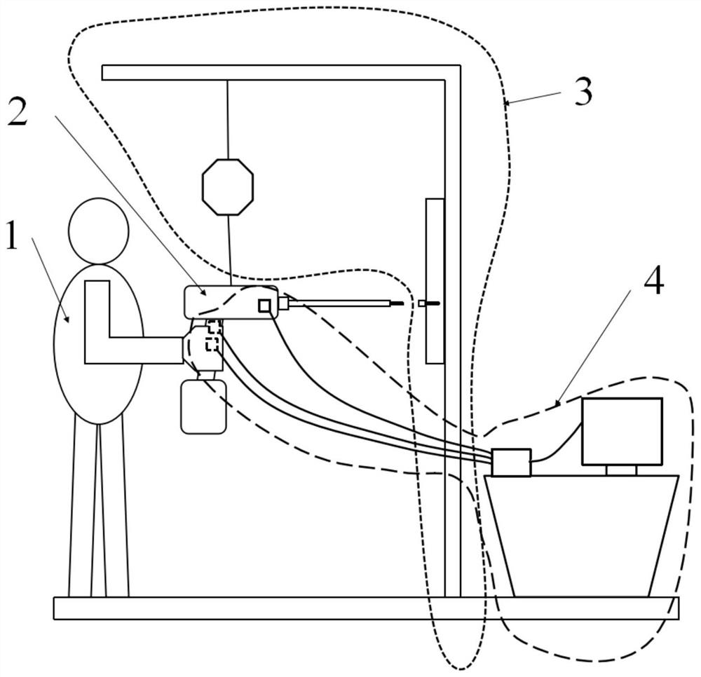
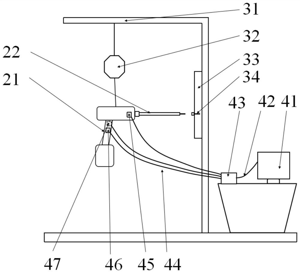
  • A measuring device for the transmission vibration of electric tools in the rail repair
  • A measuring device for the transmission vibration of electric tools in the rail repair
  • A measuring device for the transmission vibration of electric tools in the rail repair

Examples


Embodiment Construction

[0019] The technical solutions in the embodiments of the present invention will be clearly and completely described below with reference to the accompanying drawings in the embodiments of the present invention. Obviously, the described embodiments are only a part of the embodiments of the present invention, but not all of the embodiments. Based on the embodiments of the present invention, all other embodiments obtained by those of ordinary skill in the art without creative efforts shall fall within the protection scope of the present invention.

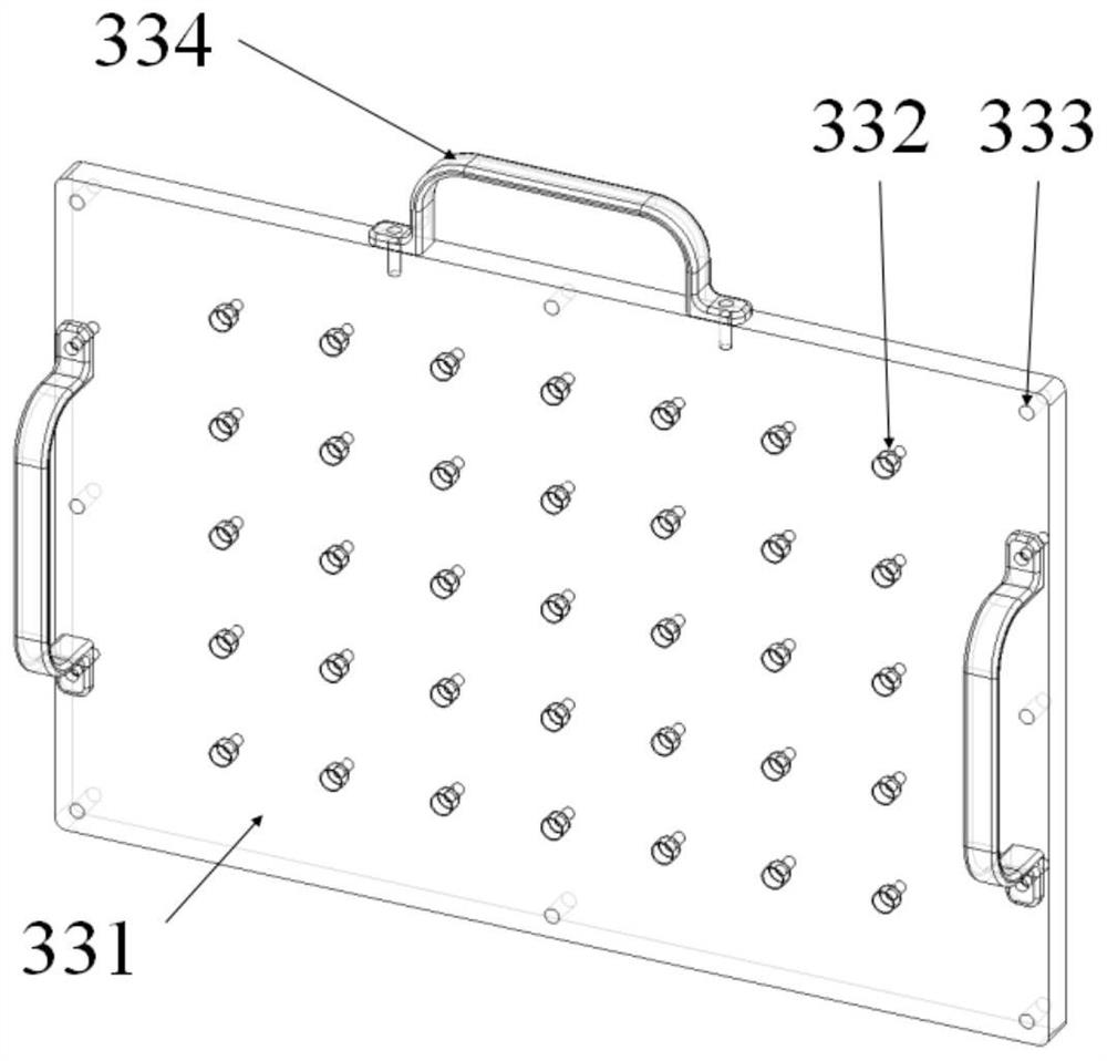
[0020] see Figure 1-3 , the present invention provides a kind of technical scheme:

[0021] A measuring device for hand-transmitted vibration of a power tool for on-orbit maintenance in space, comprising a subject 1, an on-orbit maintenance power tool 2, a suspension system 3 and a measurement system 4;

[0022] A tool handle 21 and a tool adapter rod 22 are installed on the rail maintenance power tool 2. The tool handle 21 is conve...


PUM


Abstract

The invention discloses a measuring device for hand-transmitted vibration of an electric tool for space on-orbit maintenance, comprising a subject, an on-orbit maintenance electric tool, a suspension system and a measurement system; the suspension system includes a bracket and is connected with the bracket The balancer, the screw test interface board fixed on the bracket, and the non-disengagement fastening device installed on the screw test interface board; the measurement system includes a data acquisition device and a computer, and one end of the data acquisition device passes through the data acquisition device line. cable to connect to the computer. In this application, one end of the data acquisition device is connected to the computer through a data acquisition cable, and the other end is connected to a mechanical sensor with an output axonometric point, a measurement point on the right side of the handle, and a measurement point on the left side of the handle through a sensor cable. The mechanical sensors at the measuring point on the right side of the handle and the measuring point on the left side of the handle are used to measure the vibration data of the three positions, which can assist the astronauts to better operate the on-orbit maintenance power tools.

Description

technical field [0001] The invention relates to the technical field of space on-orbit maintenance, in particular to a measuring device for hand-transmitted vibration of an electric tool used for space on-orbit maintenance. Background technique [0002] One of the space on-orbit maintenance work is the on-orbit maintenance and replacement of equipment. It is necessary to disassemble and install the mounting screws of the fixed equipment on-orbit. This process will use a variety of special tools. An on-orbit maintenance power tool, which is used by astronauts outside the cabin after wearing an extravehicular space suit. The tool is driven by a motor to rotate an adaptor rod, and the mechanical vibration generated by the rotation of the motor and the adaptor rod under microgravity is transmitted to the astronaut's gloves. , and then transmitted to the astronauts' palms, arms and even shoulders. Excessive hand-transmitted vibration may lead to fatigue of the astronauts' heads, p...

Claims


Application Information

Patent Timeline
Patent Type & Authority Patents(China)
IPC IPC(8): G01M7/02G01N3/34
CPCG01M7/025G01M7/022G01N3/34G01N2203/0005G01N2203/0676
Inventor 傅浩于洋郑鹏张春元王哲武婷婷郭涛
Owner BEIJING INST OF SPACECRAFT ENVIRONMENT ENG
Learn More