
Inverter device

A technology of inverters and switching elements, applied in the direction of controlling electromechanical transmission devices, output power conversion devices, and controlling electromechanical brakes, etc., can solve problems such as common-mode noise, eliminate or suppress common-mode noise, and simplify calculations Effect

Pending Publication Date: 2022-03-01
三电株式会社
View PDF4 Cites 0 Cited by
  • Summary
  • Abstract
  • Description
  • Claims
  • Application Information

AI Technical Summary

Problems solved by technology

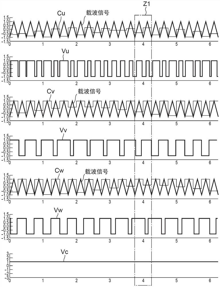
[0005] The neutral point potential Vc of the motor is calculated by the average value of the voltage of each phase (Vu+Vv+Vw) / 3, but in the past, such as Figure 7 As shown in the bottom row of , since the neutral point potential Vc fluctuates, there is a problem that common mode noise is generated

Method used


Image

  • Inverter device
  • Inverter device
  • Inverter device

Examples


Embodiment Construction

[0043] Hereinafter, embodiments of the present invention will be described in detail based on the drawings. The inverter device 1 of the embodiment is mounted on a so-called inverter-integrated electric compressor in which a compression mechanism is driven by a motor 8, and the electric compressor constitutes, for example, a refrigerant circuit of a vehicle air conditioner.

[0044] (1) Structure of the inverter device 1

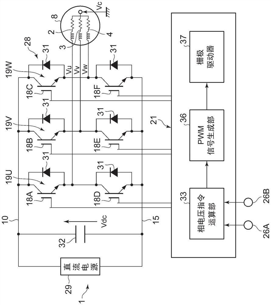
[0045] figure 1 Among them, the inverter device 1 includes a three-phase inverter circuit 28 and a control device 21 . The inverter circuit 28 is a circuit that converts a DC voltage of a DC power supply (vehicle battery, eg, 300 V) 29 into a three-phase AC voltage and applies it to the motor 8 . This inverter circuit 28 has a U-phase half-bridge circuit 19U, a V-phase half-bridge circuit 19V, and a W-phase half-bridge circuit 19W, and each phase half-bridge circuits 19U to 19W have upper arm switching elements 18A to 18C and lower arm switching elements ...


PUM


Abstract

The invention provides an inverter device capable of effectively eliminating or suppressing common-mode noise in consideration of the influence of dead time by using the function of a PWM signal generation unit. The control device (21) is provided with: a phase voltage command calculation unit (33) for calculating a three-phase modulation voltage command value for generating a voltage applied to each phase of the motor (8); and a PWM signal generation unit (36) that generates a PWM signal for PWM control of the inverter circuit (28) on the basis of the three-phase modulation voltage command value and an individual carrier signal, the PWM signal generation unit (36) correcting the three-phase modulation voltage command value output from the phase voltage command calculation unit (33), thereby canceling a change in the phase voltage applied to the motor (8) by a change in the other phase voltage.

Description

technical field [0001] The present invention relates to an inverter device driven by applying an AC voltage to a motor through an inverter circuit. Background technique [0002] Conventional inverter devices used to drive motors consist of multiple switching elements to form a three-phase inverter circuit, and PWM (Pulse Width Modulation: Pulse Width Modulation) control is performed on the switching elements of each UVW phase, and by applying a nearly sinusoidal Wave voltage waveform to drive. [0003] Figure 7 It shows the three-phase modulation voltage command values ​​Vu', Vv', Vw', carrier signal, U-phase voltage Vu, V-phase voltage Vv, and W-phase voltage Vw of each phase voltage in the conventional inverter device (PWM signal) and the graph of the neutral point voltage Vc of the motor. The unillustrated phase voltage command calculation unit calculates the three-phase modulated voltage command values ​​Vu' (U-phase voltage command value), Vv' ( V-phase voltage comm...

Claims


Application Information

Patent Timeline
Patent Type & Authority Applications(China)
IPC IPC(8): H02M7/5387H02P27/08H02P21/14H02P21/22
CPCH02M7/53871H02P27/08H02P21/14H02P21/22H02M7/5395H02M1/123H02M1/38H02M1/084
Inventor 柏原辰树
Owner 三电株式会社
Learn More