Inverter device

A technology of inverters and control devices, which is applied in the direction of converting irreversible DC power input into AC power output to achieve the effect of suppressing common mode noise and eliminating or common mode noise.

Pending Publication Date: 2021-09-28
三电株式会社
View PDF0 Cites 0 Cited by
  • Summary
  • Abstract
  • Description
  • Claims
  • Application Information

AI Technical Summary

Problems solved by technology

[0002] Conventionally, in an inverter device for driving a motor, a three-phase inverter circuit is constructed by using a plurality of switching elements, and PWM (Pulse Width Modulation: Pulse Width Modulation) control is performed on the switching elements of each phase of the UVW, so as to approach A sinusoidal voltage waveform is applied to the motor to drive it, but common mode noise due to fluctuations in the neutral point potential of the motor becomes a problem

Method used


Image

  • Inverter device
  • Inverter device
  • Inverter device

Examples


Embodiment Construction

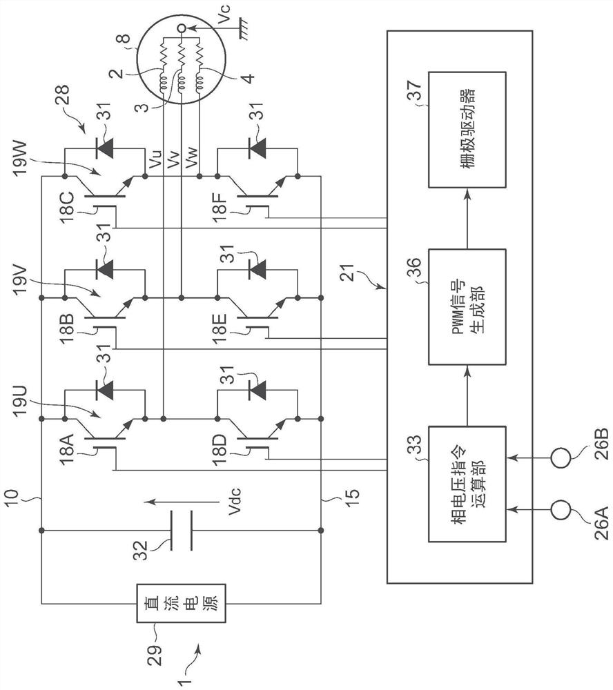
[0032] Hereinafter, embodiments of the present invention will be described in detail based on the drawings. The inverter device 1 of the embodiment is mounted on a so-called inverter-integrated electric compressor in which a compression mechanism is driven by an electric motor 8 , and the electric compressor constitutes, for example, a refrigerant circuit of a vehicle air conditioner.

[0033] (1) Structure of the inverter device 1

[0034] figure 1 Among them, the inverter device 1 includes a three-phase inverter circuit (three-phase inverter circuit) 28 and a control device 21 . The inverter circuit 28 is a circuit that converts a DC voltage of a DC power supply (vehicle battery: eg, 300V) 29 into a three-phase AC voltage and applies it to the motor 8 . This inverter circuit 28 includes a U-phase half-bridge circuit 19U, a V-phase half-bridge circuit 19V, and a W-phase half-bridge circuit 19W. Arm switching elements 18D to 18F. In addition, a freewheel diode 31 is connec...


PUM


Abstract

Provided is an inverter device that makes it possible to effectively eliminate or reduce common mode noise. The inverter device 1 comprises an inverter circuit 28 and a control device 21. The inverter circuit connects upper arm switching elements 18A-18C and lower arm switching elements 18D-18F of respective phases in series between an upper arm power supply line 10 and a lower arm power supply line 15, and applies the voltages at the contact points between the upper and lower arm switching elements of the phases to a motor 8 as three-phase alternating-current output. The control device synchronizes the switching timing of the upper and lower arm switching elements of the phases and, by means of changes in the other phase voltages, cancels changes in the phase voltage applied to the motor.

Description

technical field [0001] The present invention relates to an inverter device that drives a motor by applying an AC voltage to it using an inverter circuit. Background technique [0002] Conventionally, in an inverter device for driving a motor, a three-phase inverter circuit is composed of a plurality of switching elements, and PWM (Pulse Width Modulation: Pulse Width Modulation) control is performed on the switching elements of each phase of the UVW, which will approach the A sinusoidal voltage waveform is applied to the motor to drive it, but common mode noise due to fluctuations in the neutral point potential of the motor poses a problem. [0003] For example, in the case of a motor constituting an electric compressor, this common mode noise is generated by a common mode current leaking through a parasitic capacitance between the casing of the compressor and the ground. Conventionally, noise filters have been installed to meet the specifications. [0004] prior art literat...

Claims


Application Information

Patent Timeline
IPC IPC(8): H02M7/48
CPCH02M7/48
Inventor 柏原辰树
Owner 三电株式会社
Why Eureka
Try Eureka