
High-applicability electricity testing self-detection warning device based on electrical equipment

A technology for warning devices and power equipment, applied in the directions of measuring devices, measuring device casings, measuring current/voltage, etc., can solve the safety hazards of electric sparks in inconvenient equipment and devices, real-time monitoring of the live condition of difficult power equipment, and inconvenient fault location location. and other problems to achieve the effect of increasing the scope of detection, preventing potential safety hazards and preventing electric shock

Pending Publication Date: 2022-03-04
JIANGSU ELECTRIC POWER CO +1
View PDF0 Cites 0 Cited by
  • Summary
  • Abstract
  • Description
  • Claims
  • Application Information

AI Technical Summary

Problems solved by technology

[0003] However, as far as the current traditional electric inspection self-detection warning device is concerned, the surface of the electric equipment will bring great potential safety hazards. It is difficult for the current electric inspection pole to monitor the live situation of the electric equipment in real time, and it is not convenient to prevent equipment from being charged in advance. And the potential safety hazards caused by the electric sparks generated by the electrification of the device itself. At the same time, the current inspection rod needs to be manually operated by the staff to detect, which is not convenient for detection in a more complicated working environment, and it is also not convenient for rapid location of the fault

Method used


Image

  • High-applicability electricity testing self-detection warning device based on electrical equipment
  • High-applicability electricity testing self-detection warning device based on electrical equipment
  • High-applicability electricity testing self-detection warning device based on electrical equipment

Examples


Embodiment

[0033] Example: Please refer to Figure 1 to 9 :

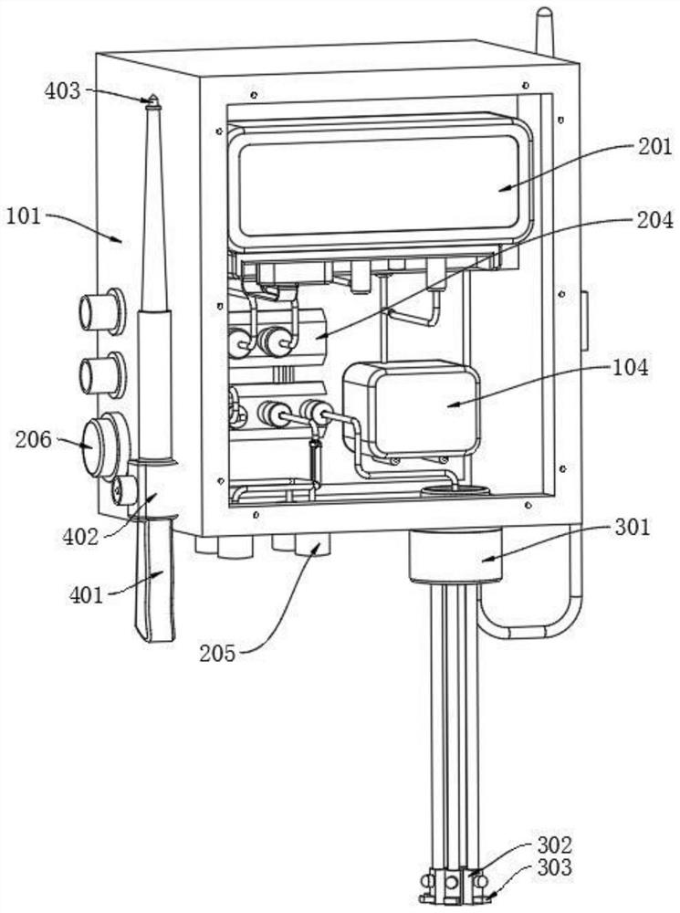
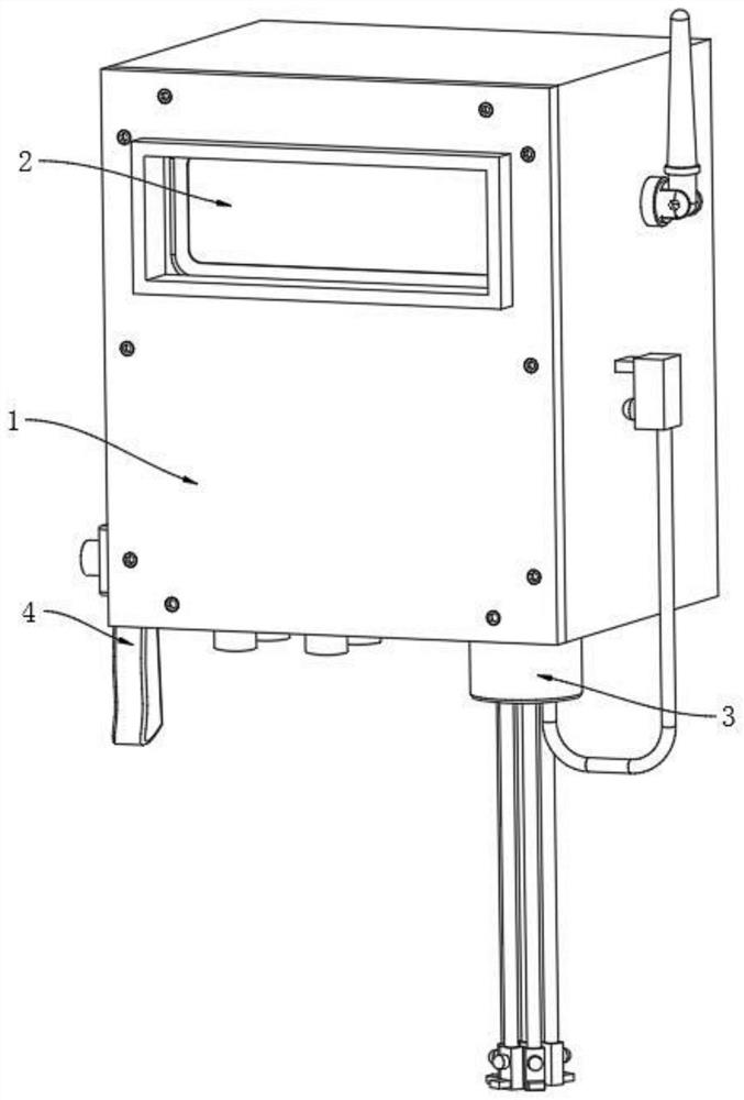
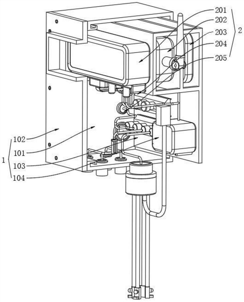
[0034] The present invention is based on the high applicability of the proposed test device from the electrical power detecting warning device, comprising: a mounting means; an internally mounted mechanism attached to the control mechanism 2, the controller 2 and the display control means and the mounting mechanism 201 of the seal 1 the cover through hole 102 is aligned; means a lower mounting means 3 is attached to the self-test, self-test means and the connecting member 3 is connected via a line 301 to the control means 2 of merged element 204; the left mounting mechanism 1 is mounted detecting means 4, the telescopic rod 4 and the detecting means 402 mounted on the card body 101 is mounted on the left side.

[0035] Further, according to an embodiment of the present invention, such as figure 1 , image 3 , The mounting mechanism 1 comprising: mounting the housing 101, the housing 101 is mounted in a rectangular configuration, mou...


PUM


Abstract

The invention provides a high-applicability electricity testing self-detection warning device based on power equipment, and relates to the technical field of power monitoring. A control mechanism is mounted in the mounting mechanism; a self-checking mechanism is mounted below the mounting mechanism; a detection mechanism is mounted on the left side of the mounting mechanism, a magnetic part of a self-checking mechanism is adsorbed on the surface of equipment needing to be monitored, and when the device is used, the device detects the equipment to be detected and the device itself at a certain time interval by setting a cycle period; the electricity testing self-detection warning device is used for preventing potential safety hazards caused by electric sparks generated by electrification of equipment and devices in advance, can prompt workers to prevent electric shock caused by mistaken touch of the workers, and solves the problem that a traditional electricity testing self-detection warning device is inconvenient to prevent the potential safety hazards caused by the electric sparks generated by electrification of the equipment and devices in advance.

Description

Technical field [0001] The present invention relates to a power monitoring technology, and more particularly relates to a test based on the high applicability of electrical power equipment from the detecting warning device. Background technique [0002] Requires a large amount of power equipment in a substation, a power current above 10KV access system, in a high pressure environment, the power device itself is likely to be charged, it will tend to experience an electrical apparatus using a high pressure electrical inspection work is completed. [0003] However, in terms of current traditional power-on self test detection warning device, after charging the surface of electrical equipment will bring a great security risk, and now the test case of the pole is difficult to live real-time monitoring of power equipment is not easy to advance prevention equipment and spark generated by the device itself charging potential safety problems, while the posterior pole current manual operati...

Claims


Application Information

Patent Timeline
IPC IPC(8): G01R19/155G01R1/04
CPCG01R19/155G01R1/0408
Inventor 苏华陶然金立我刘志芬施亮周侗
Owner JIANGSU ELECTRIC POWER CO
Learn More