Double-cavity steel slag treating drum mechanism

A processing device and drum technology, applied in the direction of recycling technology, etc., can solve the problems of troublesome cleaning of diverter block residues, etc., and achieve the effect of improving the effect of steel slag processing and simplifying the transmission system

Inactive Publication Date: 2004-03-10
BAOSHAN IRON & STEEL CO LTD
View PDF1 Cites 9 Cited by
  • Summary
  • Abstract
  • Description
  • Claims
  • Application Information

AI Technical Summary

Problems solved by technology

This structure solves the feeding problem of different viscous slag, but since the diverter block is fi

Method used


Image

  • Double-cavity steel slag treating drum mechanism
  • Double-cavity steel slag treating drum mechanism
  • Double-cavity steel slag treating drum mechanism

Examples


Embodiment Construction

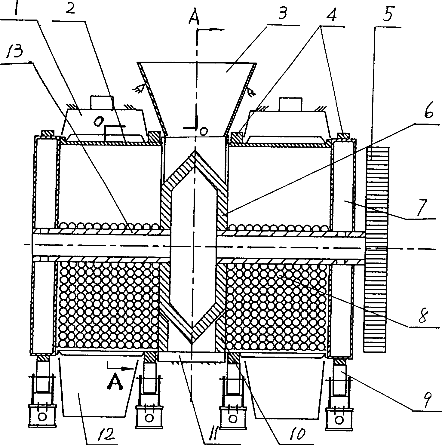
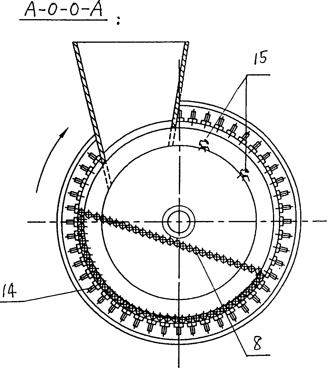
[0012] A best embodiment of the present invention is: see figure 1 and 2 The double-chamber drum steel slag processing device includes two squirrel-cage drums 2 that are partially filled with steel balls 8 in the cavity and are arranged opposite to each other on the same axis. Ring 11, a rotating splitter plate 6 is installed in the inner cavity of the fixed ring 11, the rotating shaft 13 of the splitting disc is coaxial with the drum 2, and is fixedly connected with the water cooling box 7 at the end of the drum 2, and an outer part of the rotating shaft 13 The end is fixedly connected with a transmission bull gear 5. The diverter plate 6 and its rotating shaft 13 are both hollow bodies, and the inner cavity thereof communicates with the inner cavity of the water-cooled box body 7 . There is an opening above the fixed ring 11, and its opening is slightly off to one side so that the steel slag has a longer rolling stroke in the drum 2, and a funnel 3 is inserted into the ope...


PUM


Abstract

The drum mechanism includes two coaxial cage drums with cavity filled with steel balls and opposite openings, one fixing ring between two drums, one rotating distributing disc inside the fixing ring, and one tunnel aiming at the opening over the fixing ring. The distributing disc is used to distribute steel slag, and after each slag pouring, no residual steel slag remains in the distributing disc and this solves the feeding problem of steel slag with different viscosity.

Description

Technical field: [0001] The invention relates to a device for processing steel slag, in particular to a double-chamber roller steel slag processing device. Background technique: [0002] In the Chinese invention patent application filed on December 29, 1999 with the patent application number 99127012.6, a double-chamber drum steel slag processing device is provided. It adopts two squirrel-cage rollers with opposite openings, and a wedge-shaped diverter block with a fixed ring is fixed in the middle to feed materials in a vertical direction. This structure solves the feeding problem of different viscous slags, but since the diverter block is fixed, it is troublesome to clean the residue on the diverter block after pouring the slag each time. Invention content: [0003] The purpose of the present invention is to provide an improved double-chamber drum steel slag processing device to overcome the problems in the prior art. [0004] To achieve the above object, the present i...

Claims


Application Information

Patent Timeline
IPC IPC(8): C04B5/00C21B3/06
CPCY02W30/50
Inventor 肖永力王建刚王国荣刘茵王英均曹志栋孙力活
Owner BAOSHAN IRON & STEEL CO LTD
Why Eureka
Try Eureka