
Single-line long-stroke high-speed cold pilger mill

A cold-rolled pipe mill and long-stroke technology, which is applied to the driving device for metal rolling mills, metal rolling, metal rolling, etc., can solve the problems of large inertial force and moment of inertia, complicated maintenance and adjustment, and short service life. problem, achieve the effect of reducing inertial force and moment of inertia, simple and convenient replacement and adjustment, and long service life

Inactive Publication Date: 2019-10-15
松阳永信机械制造有限公司
View PDF12 Cites 0 Cited by
  • Summary
  • Abstract
  • Description
  • Claims
  • Application Information

AI Technical Summary

Problems solved by technology

[0002] The cold-rolling mill is a process equipment for cold-rolling waste pipes with ring holes. This machine has good blanking performance and can also roll non-ferrous metal seamless pipes with ordinary precision. The biggest feature of the cold-rolling mill is Because the material utilization rate is high, and the precision and surface roughness are better than cold-drawn pipes, the cold-rolled pipe mills in the prior art have slow rolling speed, large inertial force and inertial moment of rack reciprocating motion, and unstable feeding. The service life is short and the maintenance and adjustment are complicated. Therefore, it is necessary to design a single-line long-stroke high-speed cold-rolled pipe mill

Method used


Image

  • Single-line long-stroke high-speed cold pilger mill
  • Single-line long-stroke high-speed cold pilger mill
  • Single-line long-stroke high-speed cold pilger mill

Examples


Embodiment Construction

[0016] The following will clearly and completely describe the technical solutions in the embodiments of the present invention with reference to the accompanying drawings in the embodiments of the present invention. Obviously, the described embodiments are only some, not all, embodiments of the present invention. Based on the embodiments of the present invention, all other embodiments obtained by persons of ordinary skill in the art without making creative efforts belong to the protection scope of the present invention.

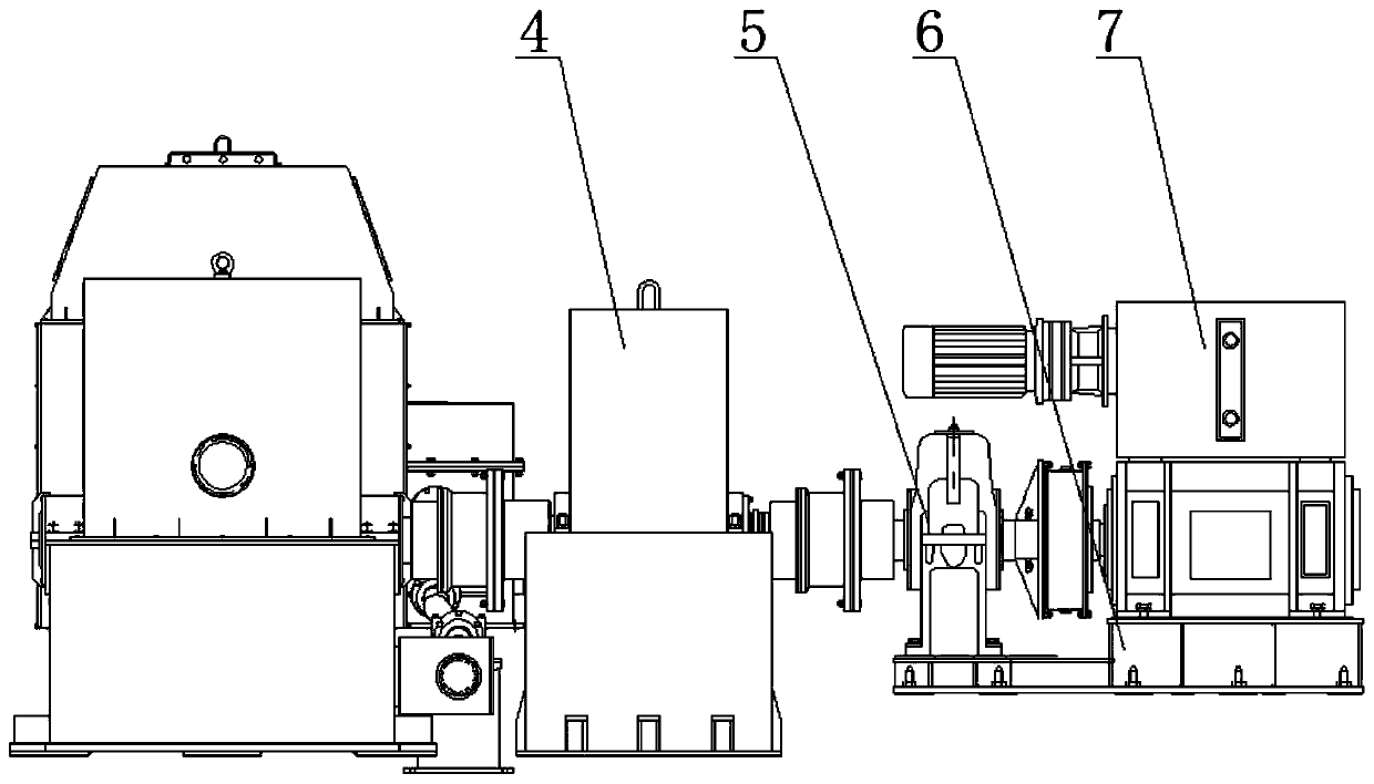
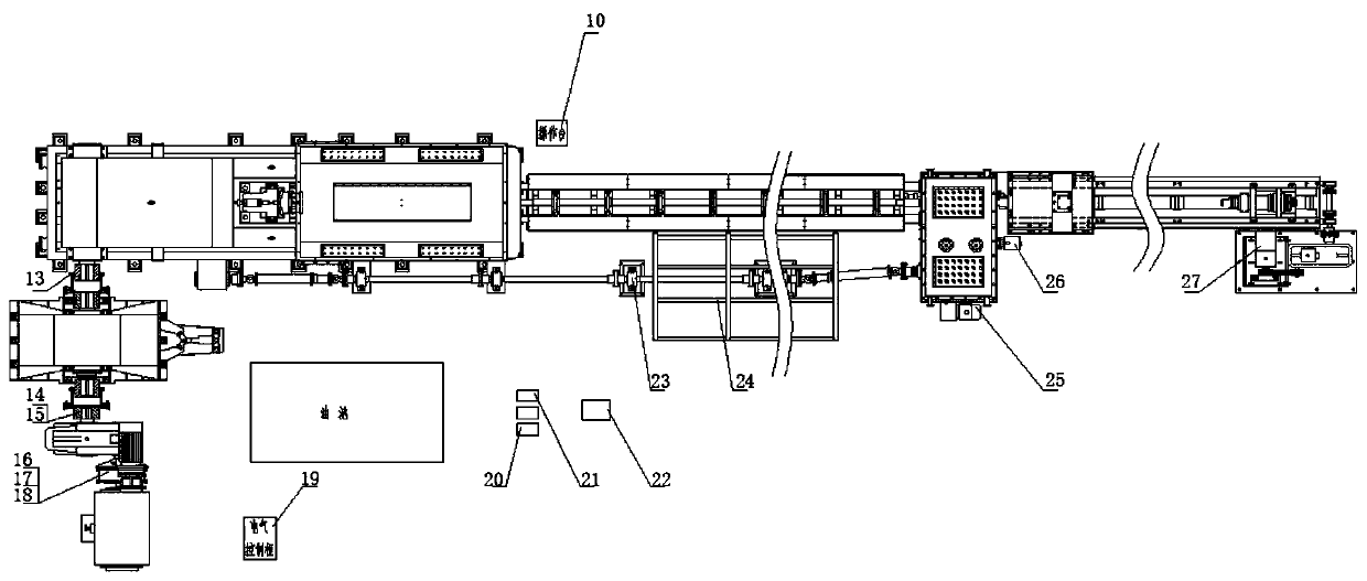
[0017] see Figure 1-3 , the present invention provides a technical solution: a single-line long-stroke high-speed cold-rolled pipe mill, including the main moving part 1 of the rail machine, the main box body 2 of the rail machine, the rotary feeding gear box 3, the flywheel box 4, and the final reducer 5 , Main power mechanism base 6, main motor 7, finished chuck box 8, screw support box 9, operation table 10, tube blank feeding trolley 11, mandrel feeding t...


PUM


Abstract

The invention discloses a single-line long-stroke high-speed pilger mill. The single-line long-stroke high-speed pilger mill comprises a rail machine main moving part, a rail machine main box, a rotary feeding gearbox, a flywheel box, a main speed reducer, a main power mechanism base, a main motor, a finished product chuck box, a lead screw supporting box, an operation table, a pipe blank feedingtrolley, a mandrel feeding trolley, a drum-shaped toothed coupling, a half coupling, an adjustment disc, an airbag clutch, a connecting sleeve, a supporting disc, an electrical control cabinet, a first lubrication motor, a second lubrication motor, a hydraulic motor, a power branch shafting, a feeding frame, a box gear lubrication motor, a fast motor and an electric motor. One side of the rail machine main moving part is connected with one side of the flywheel box through the drum-shaped toothed coupling, and the other side of the flywheel box is connected with the main speed reducer through the half coupling. According to the single-line long-stroke high-speed pilger mill, the milling speed is high, the reciprocating inertia force and the inertia moment of a rack are small, feeding is stable, the service life is long, and maintenance and adjustment are simple.

Description

technical field [0001] The invention relates to the technical field of cold-rolled pipe mills, in particular to a single-line long-stroke high-speed cold-rolled pipe mill. Background technique [0002] The cold-rolling mill is a process equipment for cold-rolling waste pipes with ring holes. This machine has good blanking performance and can also roll non-ferrous metal seamless pipes with ordinary precision. The biggest feature of the cold-rolling mill is Because the material utilization rate is high, and the precision and surface roughness are better than cold-drawn pipes, the cold-rolled pipe mills in the prior art have slow rolling speed, large inertial force and moment of inertia in the reciprocating motion of the stand, and unstable feeding. The service life is short, and maintenance and adjustment are complicated. Therefore, it is necessary to design a single-line long-stroke high-speed cold-rolled pipe mill. Contents of the invention [0003] The object of the pres...

Claims


Application Information

Patent Timeline
Patent Type & Authority Applications(China)
IPC IPC(8): B21B17/06B21B25/06B21B35/08B21B39/02
CPCB21B17/06B21B25/06B21B35/08B21B39/02
Inventor 李宪寿冯传峰陈劲松
Owner 松阳永信机械制造有限公司
Learn More