Drawing pressing equipment for computer image-text making

A graphic and drawing technology, applied in the field of drawing pressing equipment for computer graphic production, can solve problems such as troublesome fixing methods, high cost, and complicated equipment structure, and achieve the effects of reducing production costs, improving work efficiency, and simplifying equipment structure

Active Publication Date: 2022-03-04
上海赤麟科技有限公司
View PDF9 Cites 1 Cited by
  • Summary
  • Abstract
  • Description
  • Claims
  • Application Information

AI Technical Summary

Problems solved by technology

[0005] When the equipment arranges and fixes the drawings, it needs to manually pull out the clamping board after the movement of the moving board is completed, so as to realize the clamping and fixing of the drawings. This kind of fixing method is more troublesome, and the equipment structure is complicated and the cost is high

Method used


Image

  • Drawing pressing equipment for computer image-text making
  • Drawing pressing equipment for computer image-text making
  • Drawing pressing equipment for computer image-text making

Examples


Embodiment 1

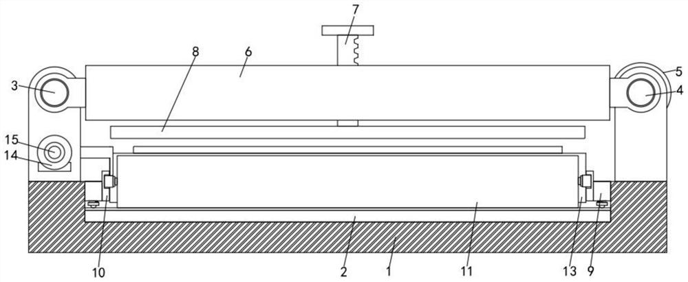
[0026] Such as figure 1 As shown, a kind of drawing pressing equipment for computer graphics and text production proposed by the present invention includes a base 1, a placement plate 2, a guide rod 3, a screw rod 4, a motor 5, a moving box 6, a tooth plate 7 and a scanner main body 8 . The top of the placement plate 2 is provided with a limiting mechanism 9 located on the inner walls of both sides of the base 1 , and the inner side of the limiting mechanism 9 is welded with a side plate 10 . A plurality of rollers 11 are movably connected between the symmetrically arranged side plates 10 , and clamping mechanisms 13 are arranged on the sides of the rollers 11 . A riser 16 is welded to the front and back of the top of the base 1, and a wedge 17 is fixedly connected to the top of the riser 16. The bottom of guide rod 3 is rotatably connected with the two-way screw mandrel 15 that is positioned at the symmetrical supporting plate of left side, and the front end of two-way scre...

Embodiment 2

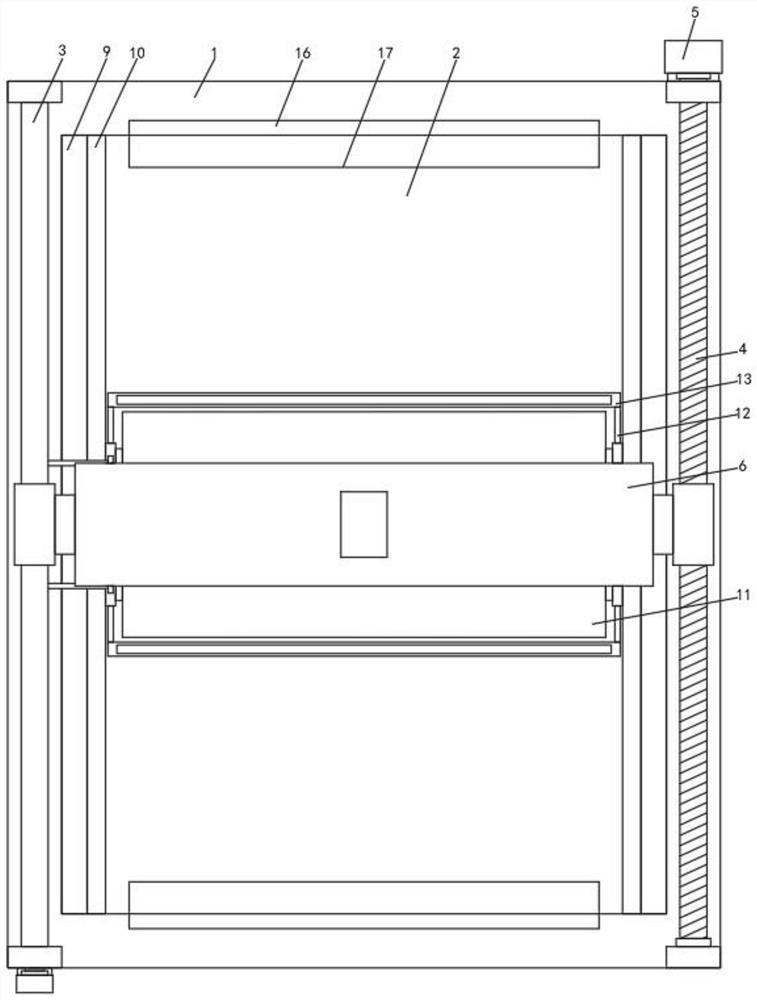
[0029] Such as Figure 1-2 As shown, the present invention proposes a drawing pressing device for computer graphics and text production. Compared with Embodiment 1, this embodiment also includes: support plates are symmetrically arranged on both sides of the top of the base 1, and support plates are symmetrically arranged on the right side. A screw 4 is connected to the plate for rotation, a motor 5 is arranged at one end of the back of the screw 4, and a guide rod 3 is arranged between the support plates arranged symmetrically on the left side, and a connecting block is set on the guide rod 3 and the screw rod 4 , a moving box 6 is arranged between a plurality of connecting blocks, a toothed plate 7 is movably connected to the moving box 6, the bottom end of the toothed plate 7 passes through the top and bottom shell walls of the moving box 6, and a scanner main body 8 is installed, The bottom inner wall of the base 1 is provided with a placement plate 2, and a chute is provi...

Embodiment 3

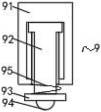
[0032] Such as Figure 3-4 As shown, the present invention proposes a drawing pressing device for computer graphics and text production. Compared with Embodiment 1 or Embodiment 2, this embodiment also includes: the limit mechanism 9 includes a limit plate 91, an adjustment rod 92, a stopper Plate 93, ball 94 and back-moving spring one 95, the inside of limit plate 91 is slidingly connected with adjusting rod 92, the bottom end of adjusting rod 92 is welded with abutment plate 93, and the bottom of abutment plate 93 is rollingly connected with a plurality of balls 94, and Adjusting rod 92 is provided with back-moving spring one 95, and clamping mechanism 13 includes cavity plate 131, movable bar 132, wedge two 133, pressing plate 134 and back-moving spring two 135, and the inner sliding connection of cavity plate 131 has many A movable rod 132, the top of a plurality of movable rods 132 is welded with two wedges 133, and the bottom end of the movable rods 132 is fixedly connec...


PUM


Abstract

The invention relates to drawing pressing equipment for computer image-text making, and belongs to the technical field of pressing equipment. In order to solve the problem that existing equipment needs to be manually adjusted when a drawing is fixed, the technical scheme is provided that the device comprises a base, a placement plate, a guide rod, a lead screw, a first motor, a moving box, a toothed plate and a scanner body, and limiting mechanisms located on the inner walls of the two sides of the base are arranged above the placement plate. Through the combination of various structures, the device not only can be used for arranging drapes and stretching drawings and fixing the drawings, but also can be used for realizing efficient arrangement and convenient clamping of the drawings through the combination of a motor II, a bidirectional screw rod, a side plate, a roller, a clamping mechanism, a vertical plate and a wedge block I; and the limiting mechanism is arranged to primarily tidy the drawings when the drawings are placed, so that the trouble of later tidying is reduced, a mechanism for tidying the drawings in the prior art is replaced, the working efficiency is improved, the equipment structure is simplified, and the production cost of the equipment is reduced.

Description

technical field [0001] The invention relates to the technical field of pressing equipment, in particular to a drawing pressing equipment for computer graphics and text production. Background technique [0002] The use of scanners is indispensable in graphic production. Scanners can quickly scan and copy drawings in large quantities, and are widely used in signage panels, printed boards, and printing industries. Some drawings are large in size. In order to save space, the drawings are usually folded for storage. When the drawings are unfolded before scanning, the drawings will inevitably appear curled, which will cause the scanner to fail to scan the curled parts and need to be sorted and fixed manually. , which undoubtedly increases the workload of the staff and greatly reduces work efficiency. [0003] There is an existing Chinese patent whose authorized notification number is CN214591577U, which discloses a drawing fixing device for large-scale drawing scanning equipment,...

Claims


Application Information

Patent Timeline
Patent Type & Authority Applications(China)
IPC IPC(8): H04N1/00H04N1/04
CPCH04N1/00647H04N1/00567H04N1/04
Inventor 杨晓银张文静
Owner 上海赤麟科技有限公司
Why Eureka
Try Eureka