
Intelligent power grid fault positioning method and device

A smart grid and fault location technology, applied in the direction of instruments, character and pattern recognition, data processing applications, etc., can solve the problems of power grid layout, fault location is not accurate, fault monitoring process has not reached a mature stage, etc., to reduce maintenance costs, The effect of improving failure efficiency

Pending Publication Date: 2022-03-08
CHINA SOUTHERN POWER GRID DIGITAL GRID RES INST CO LTD
View PDF0 Cites 0 Cited by
  • Summary
  • Abstract
  • Description
  • Claims
  • Application Information

AI Technical Summary

Problems solved by technology

[0002] The focus of smart grid intelligence lies in the power supply stage. Many researchers in this field are concentrating on how to supply power in the power supply stage. Therefore, the research on the power supply stage is becoming more and more mature, but the research on the fault monitoring process has not yet reached the mature stage. The existing fault monitoring process is attached to the existing circuit system, adding some current or voltage detection equipment, and then performing fault location based on the obtained voltage or current data
However, due to cost issues, it is impossible to install current or voltage detection equipment for each branch line of the power grid, and the current or voltage detection equipment is also easily damaged, and the problem of inaccurate fault location is prone to occur

Method used


Image

  • Intelligent power grid fault positioning method and device
  • Intelligent power grid fault positioning method and device
  • Intelligent power grid fault positioning method and device

Examples


Embodiment 1

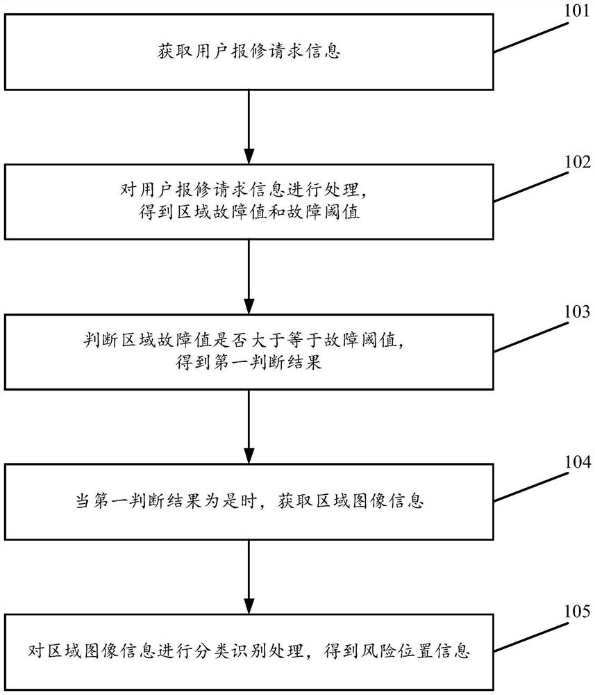
[0078] see figure 1 , figure 1 It is a schematic flowchart of a smart grid fault location method disclosed in an embodiment of the present invention. in, figure 1 The described smart grid fault location method is applied to a fault processing system, such as a local server or a cloud server used for smart grid fault location management, which is not limited in the embodiments of the present invention. Such as figure 1 As shown, the smart grid fault location method may include the following operations:

[0079] 101. Obtain the user's repair request information.

[0080] In the embodiment of the present invention, the above user repair request information includes several user repair requests.

[0081] 102. Process the user repair request information to obtain the regional fault value and fault threshold.

[0082] 103. Determine whether the area fault value is greater than or equal to the fault threshold, and obtain a first judgment result.

[0083] 104. Acquire area imag...

Embodiment 2

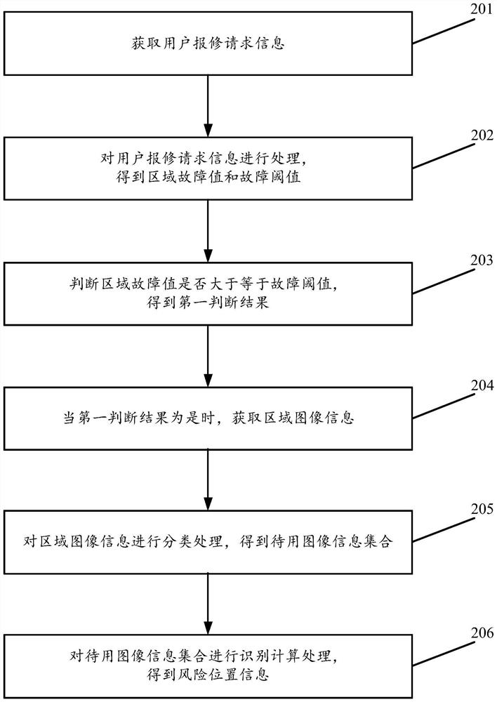
[0129] see figure 2 , figure 2 It is a schematic flowchart of another smart grid fault location method disclosed in the embodiment of the present invention. in, figure 2 The described smart grid fault location method is applied to a fault processing system, such as a local server or a cloud server used for smart grid fault location management, which is not limited in the embodiments of the present invention. Such as figure 2 As shown, the smart grid fault location method may include the following operations:

[0130] 201. Obtain the user's repair request information.

[0131] 202. Process the user repair request information to obtain an area fault value and a fault threshold.

[0132] 203. Judging whether the regional fault value is greater than or equal to the fault threshold, and obtaining a first judgment result.

[0133] 204. Acquire area image information when the first determination result is yes.

[0134] 205. Classify and process the regional image informati...

Embodiment 3

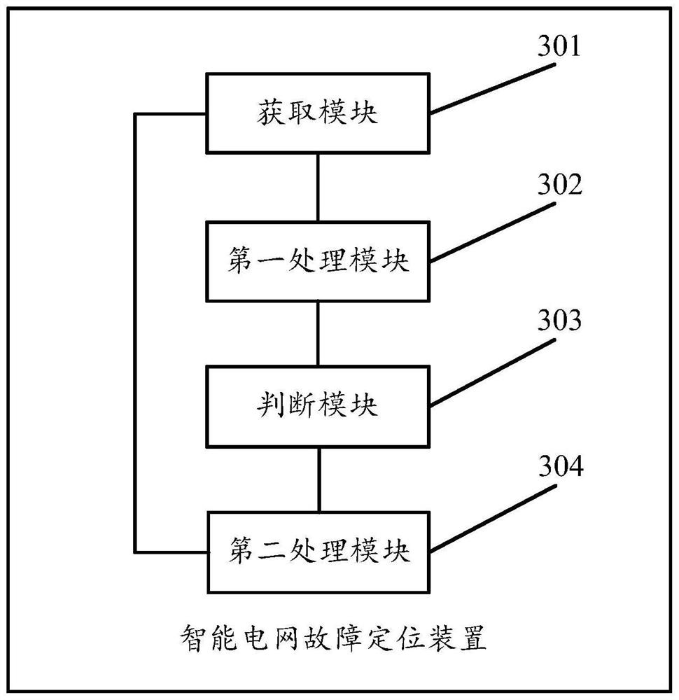
[0165] see image 3 , image 3 It is a schematic structural diagram of a smart grid fault location device disclosed in an embodiment of the present invention. in, image 3The described device can be applied to a fault processing system, such as a local server or a cloud server for smart grid fault location management, which is not limited by the embodiments of the present invention. Such as image 3 As shown, the device may include:

[0166] An acquisition module 301, configured to acquire user repair request information; the user repair request information includes several user repair requests;

[0167] The first processing module 302 is used to process the user repair request information to obtain the regional fault value and fault threshold;

[0168] A judging module 303, configured to judge whether the regional fault value is greater than or equal to the fault threshold, and obtain a first judgment result;

[0169] The acquisition module 301 is also used to acquire r...


PUM


Abstract

The invention discloses an intelligent power grid fault positioning method and device. The method comprises the following steps: obtaining repair request information of a user; processing the repair request information of the user to obtain a regional fault value and a fault threshold value; judging whether the regional fault value is greater than or equal to a fault threshold to obtain a first judgment result; when the first judgment result is yes, obtaining regional image information; the regional image information comprises a plurality of pieces of high-risk point image information; the smart grid power supply area to which the area image information belongs is consistent with the smart grid power supply area to which the user repair request information belongs; performing classification identification processing on the regional image information to obtain risk position information; the risk position information comprises a plurality of pieces of risk point information; the risk position information is used for indicating the positioning of the fault of the smart grid. Therefore, accurate fault positioning of the smart power grid is realized, the fault efficiency is improved, and the maintenance cost of the power grid is reduced.

Description

technical field [0001] The invention relates to the technical field of fault location, in particular to a smart grid fault location method and device. Background technique [0002] The focus of smart grid intelligence lies in the power supply stage. Many researchers in this field are concentrating on how to supply power in the power supply stage. Therefore, the research on the power supply stage is becoming more and more mature, but the research on the fault monitoring process has not yet reached the mature stage. The existing fault monitoring process is to attach to the existing circuit system, add some current or voltage detection equipment, and then perform fault location according to the obtained voltage or current data. However, due to cost issues, it is impossible to install current or voltage detection equipment on each branch line of the power grid, and the current or voltage detection equipment is also easily damaged, which is prone to inaccurate fault location. . ...

Claims


Application Information

Patent Timeline
IPC IPC(8): G06Q10/06G06Q50/06G06V10/764G06K9/62
CPCG06Q10/06G06Q50/06G06F18/24
Inventor 刘静仪宁桂华李敏赵继光刘天虎王庭松陈强
Owner CHINA SOUTHERN POWER GRID DIGITAL GRID RES INST CO LTD
Learn More