Dispensing equipment for wireless charging module

A wireless charging and dispensing technology, which is applied in the direction of surface coating liquid devices, coatings, pretreatment surfaces, etc., can solve the problems of reducing dispensing efficiency, reducing the amount of glue at solder joints, and dispensing height collapse. Achieve the effect of improving the protection effect, increasing the dispensing height, and reducing the probability of diffusion

Inactive Publication Date: 2022-03-11
东莞市海联科技有限公司
View PDF1 Cites 0 Cited by
  • Summary
  • Abstract
  • Description
  • Claims
  • Application Information

AI Technical Summary

Problems solved by technology

[0003] The patent document publication number is CN209362876U, which discloses a new type of high-efficiency automatic UV dispensing and bonding equipment. It is proposed in the background technology that when the circuit board is dispensing, it is usually manually dispensing and curing in an assembly line, and the work efficiency is low; while the wireless charging model When the group is dispensing glue, it often gathers a certain number of products for pre-baking after dispensing a single charging module, which cannot be continuously produced and reduces the efficiency of dispensing; because the glue is fluid, it will make the glue solder joints External diffusion, the dispensing height collapses, thereby reducing the amount of glue at the solder joint position, thereby reducing the protective effect of the glue on the solder joints, so we need to propose a wireless charging module dispensing equipment

Method used


Image

  • Dispensing equipment for wireless charging module
  • Dispensing equipment for wireless charging module
  • Dispensing equipment for wireless charging module

Examples


Embodiment Construction

[0032] In order to make the purpose, technical solutions and advantages of the embodiments of the present invention more clear, the technical solutions in the embodiments of the present invention will be clearly and completely described below in conjunction with the accompanying drawings in the embodiments of the present invention. Obviously, the described embodiments It is a part of embodiments of the present invention, but not all embodiments. Based on the embodiments of the present invention, all other embodiments obtained by persons of ordinary skill in the art without making creative efforts belong to the protection scope of the present invention.

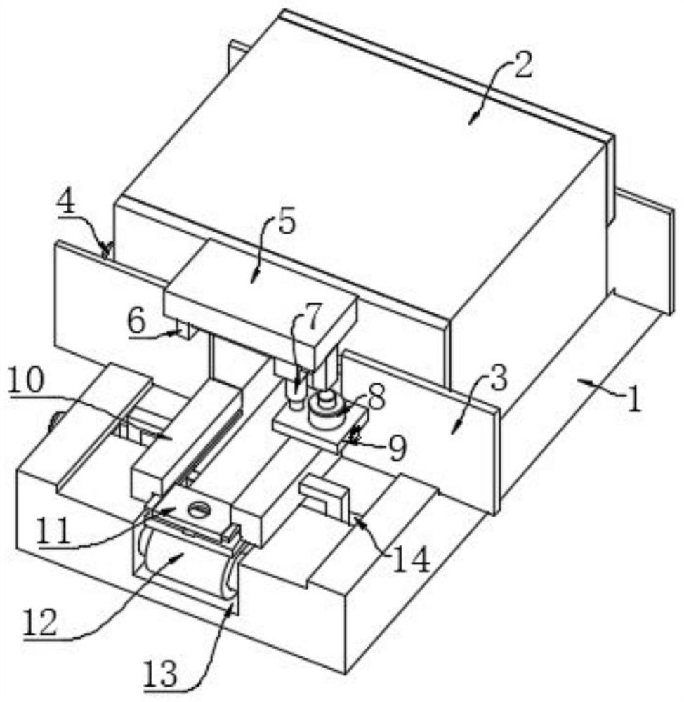
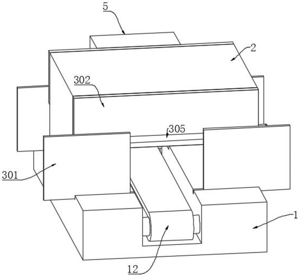
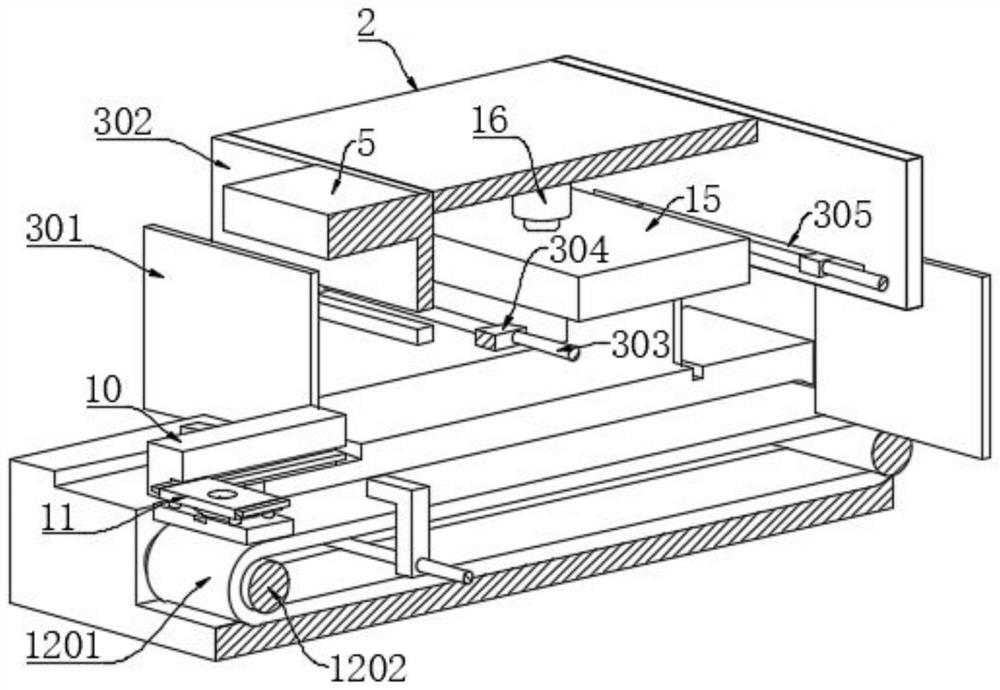
[0033] The embodiment of the present invention provides a wireless charging module dispensing equipment, such as Figure 1 to Figure 3 As shown, it includes a workbench 1, a pre-oven 2, a thermal insulation assembly 3, a dispensing assembly 8, a fixing assembly 9, a limit assembly 10, a loading assembly 11 and a transmission a...


PUM


Abstract

The invention relates to the technical field of wireless charging module production, in particular to wireless charging module dispensing equipment which comprises a workbench, a pre-baking oven, a heat insulation assembly, a dispensing assembly, a fixing assembly, a limiting assembly, a material carrying assembly and a conveying assembly. Material carrying assemblies of different sizes can be made according to the size of an actually produced wireless charging module, the moving positions of the material carrying assemblies are limited through the limiting assembly, the conveying assembly can conveniently drive a material carrying plate to move directionally, the dispensing assembly is detachably arranged through cooperation of the dispensing assembly and the fixing assembly, and the dispensing efficiency is improved. The glue solution can be conveniently added in time after the glue solution is used up; through cooperation of the transmission assembly, the glue dispensing assembly and the heating assembly, glue can be directly pre-baked after glue dispensing of the wireless charging module, the probability that the glue diffuses to the outside of a welding spot is reduced, and therefore the glue dispensing height of the glue at the welding spot is increased, and the protection effect of the glue on the welding spot is improved.

Description

technical field [0001] The invention belongs to the technical field of wireless charging module production, in particular to a wireless charging module dispensing equipment. Background technique [0002] The wireless charging module is mainly a charging module formed by combining a coil for electromagnetic induction with a circuit board. In the production of wireless charging modules, in order to increase the stability of the combination of the coil and the circuit board, it is usually reinforced at the welding point after the coil and the circuit board are welded. [0003] The patent document publication number is CN209362876U, which discloses a new type of high-efficiency automatic UV dispensing and bonding equipment. It is proposed in the background technology that when the circuit board is dispensing, it is usually manually dispensing and curing in an assembly line, and the work efficiency is low; while the wireless charging model When the group is dispensing glue, it o...

Claims


Application Information

Patent Timeline
Patent Type & Authority Applications(China)
IPC IPC(8): B05C5/02B05C9/14B05C11/10B05C13/02B05D3/02
CPCB05C5/0208B05C13/02B05C9/14B05C11/1047B05D3/0254
Inventor 杨学武
Owner 东莞市海联科技有限公司
Why Eureka
Try Eureka