Intelligent pneumatic flanging mechanism

A flanging and intelligent technology, applied in the field of packaging can manufacturing, can solve problems such as unfavorable manufacturing and complex structure, and achieve the effects of ensuring stable and reliable manufacturing, demoulding, and fast and reliable production

Inactive Publication Date: 2022-03-11
SUZHOU HYCAN HLDG CO LTD
View PDF0 Cites 0 Cited by
  • Summary
  • Abstract
  • Description
  • Claims
  • Application Information

AI Technical Summary

Problems solved by technology

[0002] When making packaging cans, it is necessary to perform flanging of the top side. The existing top side flanging has a complicated structure, and in actual production, the cans will be taken away from the pallet during the demoulding process, which requires manual folding. Tank reset, which is not conducive to manufacturing

Method used


Image

  • Intelligent pneumatic flanging mechanism
  • Intelligent pneumatic flanging mechanism
  • Intelligent pneumatic flanging mechanism

Examples


Embodiment Construction

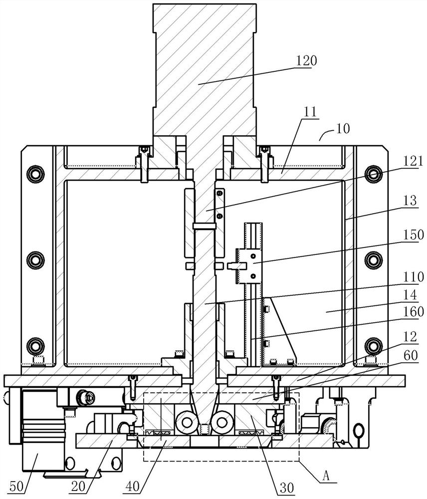
[0026] An intelligent pneumatic flanging mechanism, see Figure 1-Figure 4 , which includes:

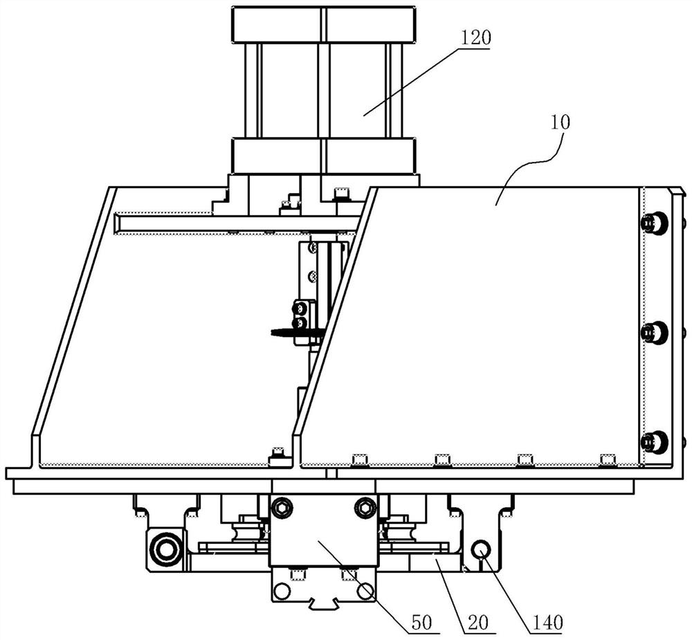
[0027] The flange frame 10 includes an upper plate 11, a lower plate 12 and two side vertical plates 13, the upper plate 11 is connected to the lower plate 12 through the two side vertical plates 13, and a cavity 14 is formed in the two side vertical plates 13;

[0028] Two flanging profiling 20;

[0029] Flange inner mold 30;

[0030] guide block 40;

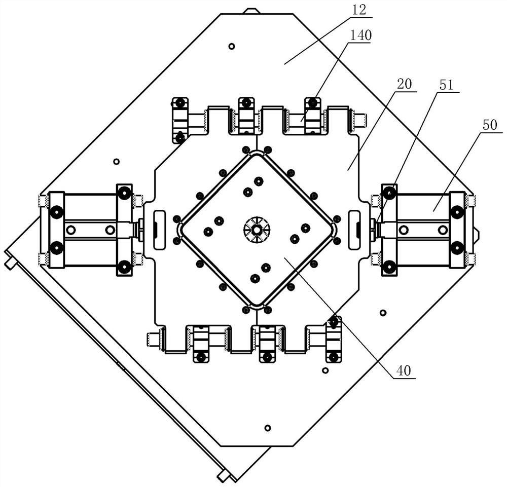
[0031] The lower surface on both sides of one of the diagonal lines of the lower plate 11 is respectively fixed with a master cylinder 50, and the piston ends 51 of the two master cylinders 50 are arranged opposite to each other, and each piston end 51 is fixedly connected with a flanging leaner on the corresponding side. Die 20, the upper surface of the inner end of the two flanging molds 20 is profilingly set in the flanging shape of the product;

[0032] The central position of the lower plate 11 is connected to the guide block...


PUM


Abstract

The invention provides an intelligent pneumatic flanging mechanism which enables flanging manufacturing to be rapid and reliable, is stable and reliable in demolding and ensures normal production and manufacturing. The flanging frame comprises an upper plate, a lower plate and two side vertical plates, the upper plate is connected with the lower plate through the two side vertical plates, and cavities are formed in the two side vertical plates; two flanging explorators are arranged; flanging the inner die; a guide block; the lower surfaces of the two sides of one diagonal line of the lower plate are fixedly provided with profile modeling air cylinders respectively, the piston ends of the two profile modeling air cylinders are oppositely arranged, each piston end is fixedly connected with a flanging profile modeling on the corresponding side, and the upper surfaces of the inner ends of the two flanging profile modeling are arranged in a manner of copying the flanging shape of a product; the center position of the lower plate is connected with a guide block through a connecting seat and a connecting column; the periphery of the guide block is arranged in a shape of an opening in the upper surface of a product; a plurality of flanging inner dies are arranged in the space between the connecting base and the guide block, and an avoiding notch is formed in the position, corresponding to the connecting column, of each flanging inner die.

Description

technical field [0001] The invention relates to the technical field of packaging can manufacturing, in particular to an intelligent pneumatic flanging mechanism. Background technique [0002] When making packaging cans, it is necessary to perform flanging of the top side. The existing top side flanging has a complicated structure, and in actual production, the cans will be taken away from the pallet during the demoulding process, which requires manual folding. The tank body is reset, which is not conducive to production. Contents of the invention [0003] In view of the above problems, the present invention provides an intelligent pneumatic flanging mechanism, which makes the flanging fast and reliable, and the demoulding is stable and reliable, ensuring normal production. [0004] An intelligent pneumatic flanging mechanism is characterized in that it comprises: [0005] The flanging frame includes an upper board, a lower board and two side vertical boards, the upper bo...

Claims


Application Information

Patent Timeline
Patent Type & Authority Applications(China)
IPC IPC(8): B21D19/08B21D37/10
CPCB21D19/08B21D37/10
Inventor 邵娜黄小林沈俊杰
Owner SUZHOU HYCAN HLDG CO LTD
Why Eureka
Try Eureka