
Layered centrifugal equipment for blood of patient in hematology department

A technology for centrifugal equipment and blood, applied in centrifuges, mechanical equipment, springs/shock absorbers, etc., can solve the problems of time-consuming blood stratification centrifugation, blood spilling, labor and other problems, and reduce the trouble of manual control of the movable plate. Effect

Pending Publication Date: 2022-03-15
何童
View PDF6 Cites 1 Cited by
  • Summary
  • Abstract
  • Description
  • Claims
  • Application Information

AI Technical Summary

Problems solved by technology

[0004] In order to overcome the time-consuming and labor-intensive manual centrifugation of blood layers, and the shortcomings of easily spilling blood when shaking the test tube, the technical problem to be solved is to provide a device that can automatically layer and centrifuge blood without causing blood to spill Blood stratification centrifuge equipment for hematology patients

Method used


Image

  • Layered centrifugal equipment for blood of patient in hematology department
  • Layered centrifugal equipment for blood of patient in hematology department
  • Layered centrifugal equipment for blood of patient in hematology department

Examples


Embodiment 1

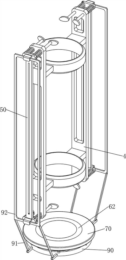
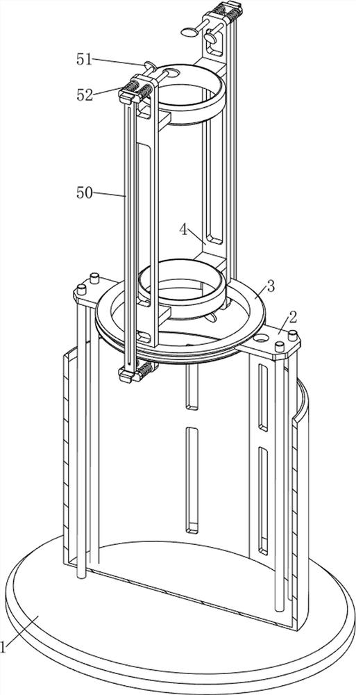
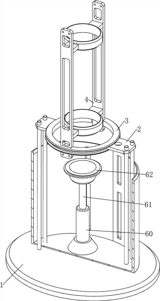
[0030] A kind of blood stratification centrifugation equipment for hematology patients, such as Figure 1-4 As shown, it includes a bottom plate 1, a support frame 2, a rotating ring 3, a fixed frame 4, a clamping mechanism 5, and a support mechanism 6. The upper left and right sides of the bottom plate 1 are connected with a support frame 2, and between the upper sides of the support frame 2 Slidingly connected with a rotating ring 3, the rotating ring 3 is connected with a fixed frame 4, the fixed frame 4 is provided with a clamping mechanism 5, and the middle upper side of the base plate 1 is provided with a supporting mechanism 6.

[0031] When the blood needs to be centrifuged in different layers, the blood can be placed in the test tube, and then the test tube containing the blood is placed on the fixed frame 4, and the bottom of the test tube is in contact with the supporting mechanism 6, and the clamping mechanism 5 can be used to hold the test tube. The test tube is f...

Embodiment 2

[0037] On the basis of Example 1, such as figure 1 , Figure 5 , Image 6 , Figure 7 , Figure 8 , Figure 9 with Figure 10 As shown, a buffer mechanism 7 is also included. The buffer mechanism 7 includes a connecting plate 70, a telescopic rod 71 and a second spring 72. The upper, front, and rear sides of the bottom plate 1 are connected with a telescopic rod 71. Between the upper side of the telescopic rod 71 A connection plate 70 is connected, and the connection plate 70 is rotatably connected with the placement table 62 , and a second spring 72 is connected between the fixed end and the telescopic end of the telescopic rod 71 .

[0038] When the bottom of the test tube filled with blood is in contact with the placement table 62, the placement table 62 will be moved downwards, thereby causing the connection plate 70 to move downwards. At this time, the force of the test tubes being pressed down will be buffered by the action of the second spring 72, thereby preventin...


PUM


Abstract

The invention relates to layered centrifugal equipment, in particular to patient blood layered centrifugal equipment for the hematology department. The technical problem to be solved by the invention is to provide the blood layering centrifugation equipment for the patient in the hematology department, which can automatically perform blood layering centrifugation and cannot cause blood scattering. A patient blood layering centrifugal device for the hematology department comprises a bottom plate, supporting frames, a rotating ring, a fixing frame, a clamping mechanism and a supporting mechanism, the supporting frames are connected to the two sides of the bottom plate, the rotating ring is slidably connected between the supporting frames, the fixing frame is connected to the rotating ring, the clamping mechanism is arranged on the fixing frame, and the supporting mechanism is arranged on the bottom plate. The device is provided with the buffer mechanism, so that the downward pressing force of the test tubes can be buffered, and the test tubes are prevented from being damaged due to too large impact force when the test tubes are in contact with the placement table.

Description

technical field [0001] The invention relates to a layered centrifugal device, in particular to a layered centrifugal device for the blood of a hematology patient. Background technique [0002] Blood is a red, opaque, viscous liquid that flows in the blood vessels and heart of a person. Its main components are plasma, blood cells, and genetic material. Blood stores human health information. Many diseases require blood tests. During the blood test, the patient's blood needs to be extracted, and then the blood is layered and centrifuged, and then the components of each part of the blood are tested. Generally, the layered centrifugation of the blood is performed manually, and the blood is manually put into the test tube, and then shaken. Test tubes, and then achieve the effect of blood layered centrifugation, but manual blood layered centrifugation is time-consuming and laborious, and it is easy to spill blood when shaking the test tube. [0003] Therefore need to design a kind...

Claims


Application Information

Patent Timeline
IPC IPC(8): B04B5/04B04B7/02B04B9/02B04B7/00F16F15/067
CPCB04B5/0414B04B7/02B04B9/02B04B7/00F16F15/067
Inventor 何童
Owner 何童
Learn More