Short thread end cutting device of column type sewing machine

A sewing machine and short thread technology, which is applied to the thread cutting mechanism, sewing machine components, sewing equipment and other directions in the sewing machine, can solve the problems that the feeding column does not have the collection function, and the debris affects the normal thread cutting.

Inactive Publication Date: 2022-03-15
徐州力达缝纫设备制造有限公司
View PDF1 Cites 1 Cited by
  • Summary
  • Abstract
  • Description
  • Claims
  • Application Information

AI Technical Summary

Problems solved by technology

[0004] However, the technical solution provided by this patent does not have a collection function on the feeding column. When the cutter cuts the short thread ends, the cut thread rags will fall directly. If the rags are not collected in time, it will be There will be technical problems that debris will accumulate for a long time and affect the normal tangent

Method used


Image

  • Short thread end cutting device of column type sewing machine
  • Short thread end cutting device of column type sewing machine
  • Short thread end cutting device of column type sewing machine

Examples


Embodiment 1

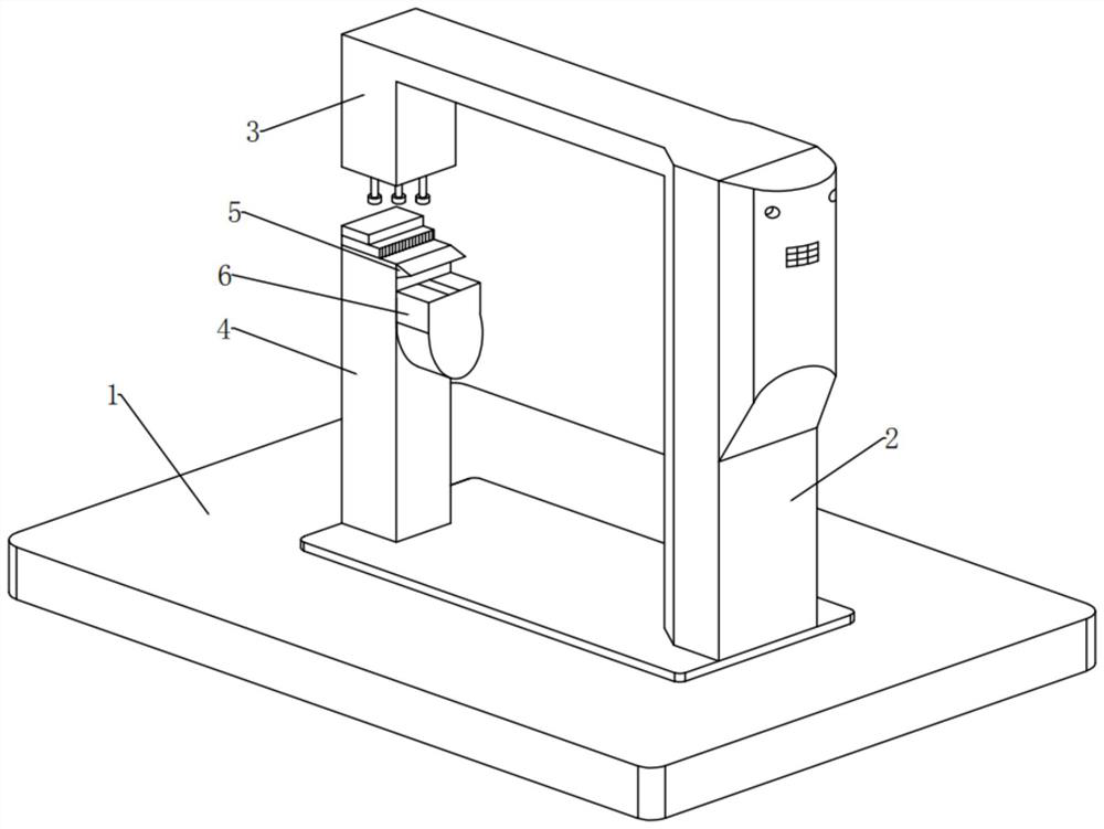
[0043] see Figure 1-2 , in an embodiment of the present invention, a short thread trimming device for a pillar sewing machine, comprising:

[0044] Base 1, a sewing machine main body 2 is fixedly installed on the top front of the base 1, a sewing machine head 3 is fixedly installed on the top rear of the sewing machine main body 1, a feeding column 4 is fixedly installed on the top rear of the base 1, and a feeding column 4 A cutter 5 is fixedly installed at the top position of the front side outer surface;

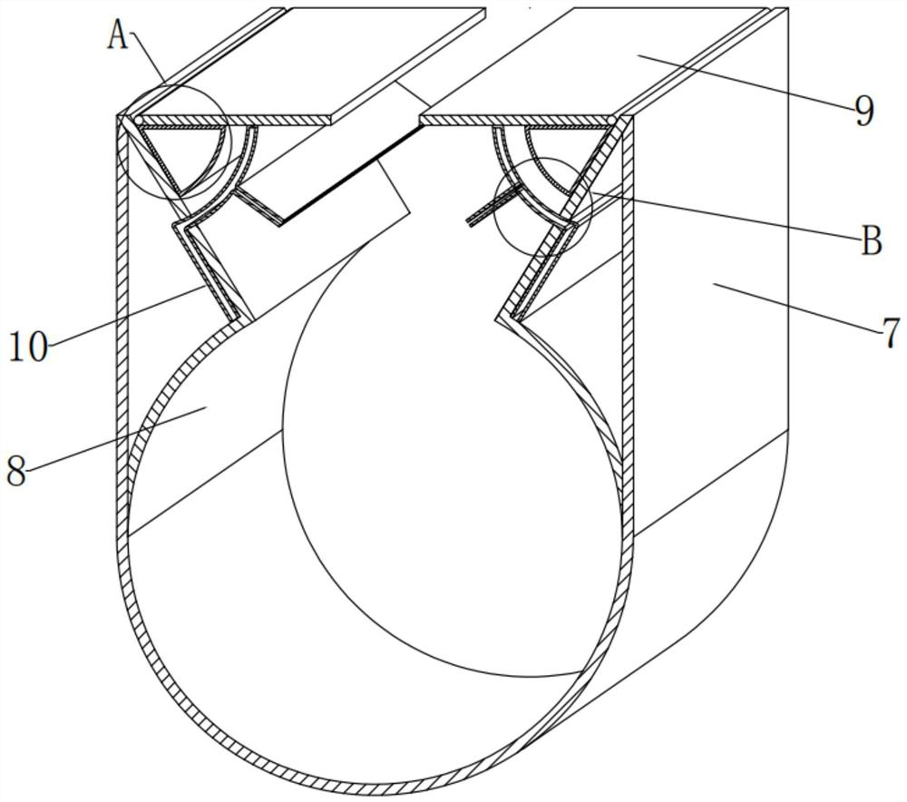
[0045] The collection assembly 6, the front outer upper end of the feeding column 4 is located directly below the cutter 5 and is fixedly equipped with a collection assembly 6 that can collect thread ends and rags. The collection assembly 6 includes: a collection shell 7, a folding plate 8, which can be controlled A material control assembly 9 for thread end rags to enter and exit and a material guide assembly 10 that can lead out the material wetted by thread end rags;...

Embodiment 2

[0059] see Figure 2-3 with Figure 5-6 , the embodiment of the present invention is different from embodiment 1 in that: the material control assembly 9 includes:

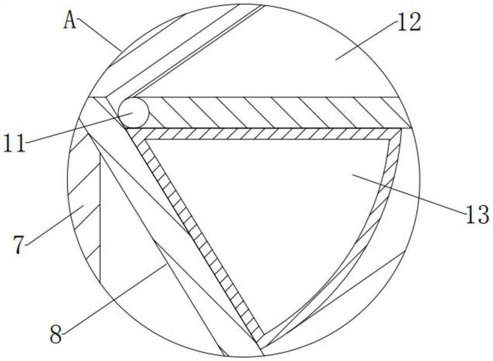
[0060] Rotating shaft 11, the left and right parts of the inner top of the collecting shell 7 are located at the top of the outer surface of the folding plate 8, and the rotating shaft 11 is installed in the front and rear horizontal direction. Location;

[0061] The rotating shaft 11 here is for the convenience of when the rags fall into the left and right ends of the top opening of the collection shell 7, it can be used as a carrier for the rotation and discharge of the rotating plate 12 at the left and right ends.

[0062] In the embodiment of the present invention, the material control assembly 9 also includes:

[0063] Turning plate 12, one side outer surface of rotating shaft 11 is surrounded and fixedly installed with turning plate 12, and turning plate 12 is in horizontal static equilibrium state under ...

Embodiment 3

[0070] see figure 2 with Figure 4-6 Compared with Embodiment 1, the embodiment of the present invention differs in that: the material guide assembly 10 includes:

[0071] Material storage tank, the inboard side of folding plate 8 and the inwall of collecting shell 7 to the top are combined to open with material storage tank. Clean water is pre-installed in the internal position of the tank, and the pre-installed amount of clean water is 2 / 3 of the internal space of the storage tank. The long through hole of the folding plate 8 is provided with an inner end inlet and an outer end outlet in the material storage tank;

[0072] The material storage tank here is set as a triangular shape with a concave bottom on a longitudinal section, which is to facilitate the storage of wet materials composed of clear water, so that the clear water can be exported when the material guide tank 14 is active in it; And the preloaded portion of clear water is 2 / 3 of the internal space of the mat...


PUM


Abstract

The invention provides a column type sewing machine short thread end cutting device which comprises a collecting assembly, and the collecting assembly capable of collecting thread ends and cloth scraps is fixedly installed at the position, located under a cutter, of the upper end of the outer surface of the front side of a feeding stand column. The collecting assembly comprises a collecting shell, a folding plate, a material control assembly capable of controlling thread residue rag to enter and exit and a material guiding assembly capable of guiding out materials wetted by the thread residue rag. A collecting shell is fixedly installed at the position, under the cutter, of the upper end of the outer surface of the front side of the feeding stand column. Folded plates are fixedly mounted between the left end and the right end of the interior of the collecting shell and the top; and material control assemblies are movably mounted on the left and right parts of the top end in the collecting shell and located at the upper ends of the outer surfaces of the folded plates. According to the short thread end cutting device of the column type sewing machine, the collecting function can be achieved on the feeding stand column, in the process that a cutter cuts a short thread end, cut thread ends and cloth waste can be collected in time, and the normal thread cutting effect is guaranteed.

Description

technical field [0001] The invention relates to the technical field of sewing machine equipment, in particular to a short thread trimming device for a column type sewing machine. Background technique [0002] When the thread trimming device of the existing sewing machine is actually used, the installation and operation of the knife plate and the thread trimmer clip are troublesome, and it is inconvenient to disassemble and maintain. Moreover, the position of the thread trimmer clip is not easy to adjust, and it is not convenient to accurately locate the thread trimming position. The mechanism for fixing the suture causes the suture to slip off easily during use, which reduces the work efficiency. [0003] In view of the above problems, regarding the technical problems such as the inconvenient disassembly and maintenance of the knife plate and the thread trimmer clamp of the existing sewing machine thread trimming device, after a large number of searches, we found a short thr...

Claims


Application Information

Patent Timeline
Patent Type & Authority Applications(China)
IPC IPC(8): D05B65/06
CPCD05B65/06
Inventor 陈文强
Owner 徐州力达缝纫设备制造有限公司
Why Eureka
Try Eureka