Bottom die slope adjusting device

A technology for adjusting device and slope, which is applied in the direction of measuring device, measuring inclination, formwork/template/work frame, etc., which can solve the problems of inability to quickly locate, incorrect installation slope of beam-shaped bottom form, etc.

Pending Publication Date: 2022-03-15
SICHUAN EAST SPRING MACHINERY EQUIP MFG CO LTD
View PDF0 Cites 0 Cited by
  • Summary
  • Abstract
  • Description
  • Claims
  • Application Information

AI Technical Summary

Problems solved by technology

[0004] The purpose of the present invention is to provide a bottom mold slope adjustment device, which solves the problem that in the prior art, when the installation slope of the beam-shaped bottom mold is wrong, it cannot be quickly positioned and adjusted

Method used


Image

  • Bottom die slope adjusting device
  • Bottom die slope adjusting device
  • Bottom die slope adjusting device

Examples


Embodiment Construction

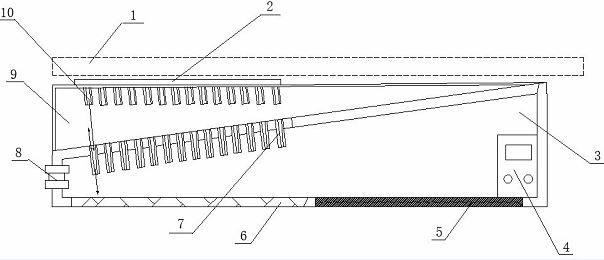
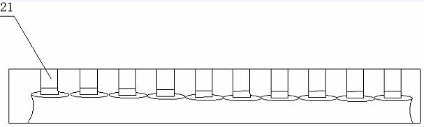
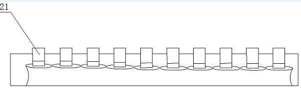
[0023] Please also refer to the attached figure 1 to the attached image 3 , this embodiment provides a bottom mold slope adjustment device, which is mainly used to solve the problem that the existing beam-shaped bottom mold cannot be quickly positioned and adjusted when the slope of the beam-shaped bottom mold is installed incorrectly. At the stage of experimental use, it should be noted that the beam-shaped bottom form in this application is formed by laying beam-shaped structural members 1 .

[0024] The specific embodiment of the present invention is as follows, including the first module 3 and the second module 9 arranged in sequence from top to bottom in the functional cavity for optical feedback work, the first module 3 and the second module 9 are fixedly connected, fixedly connected The methods include limit connection, screw fastening connection, etc. The preferred implementation mode of this embodiment is to adopt the thread fastening connection method, which can ef...


PUM


Abstract

The invention relates to the technical field of intelligent adjustment, in particular to a bottom die slope adjusting device which comprises a functional cavity, a first module and a second module which are used for light feedback operation are sequentially arranged in the functional cavity from top to bottom, and the first module is fixedly connected with the second module; a plurality of light source emitters used for emitting light rays are arranged in the first module at intervals, a plurality of light ray adjusters which are matched with the light source emitters for feedback and are arranged at intervals are arranged in the second module, and the light source emitters and the light ray adjusters are arranged, so that light ray emission and light ray adjustment can be efficiently guaranteed; information can be obtained in time, and efficient positioning can be effectively guaranteed by means of linear propagation of light.

Description

technical field [0001] The invention relates to the technical field of intelligent adjustment, in particular to a bottom mold slope adjustment device. Background technique [0002] Bottom form is a kind of template engineering. Before the construction process of the concrete project, the formwork must be supported on the construction object. For the structure in the horizontal direction, the bottom formwork needs to be supported. Such as beams, floor slabs, etc., the form of the bottom form is various, and it can be a formwork supported by tire formwork, wood formwork or other materials. [0003] In the prior art, when the bottom mold is installed and set, because it is more based on manual settings, it is impossible to find the wrong area efficiently and quickly when the slope is different, and it is also impossible to make timely and efficient adjustments after finding it, resulting in The overall construction period is easy to be delayed. Contents of the invention ...

Claims


Application Information

Patent Timeline
Patent Type & Authority Applications(China)
IPC IPC(8): G01C9/00G01C9/06E04G13/04E04G17/00
CPCG01C9/00G01C9/06E04G13/04E04G17/00G01C2009/066
Inventor 于建罗龙聪
Owner SICHUAN EAST SPRING MACHINERY EQUIP MFG CO LTD
Why Eureka
Try Eureka