
Alarm device based on electromagnetic wave emission base

An alarm device and electromagnetic wave technology, applied in alarms, electrical components, transportation and packaging, etc., can solve the problems of inconvenient maintenance and replacement of components, affecting the normal operation of microwaves, and the risk of screw slippage, etc., to achieve convenient maintenance and replacement components, reduce mutual interference, and quickly disassemble the effect

Pending Publication Date: 2022-03-15
北京九九之声科技有限公司
View PDF0 Cites 0 Cited by
  • Summary
  • Abstract
  • Description
  • Claims
  • Application Information

AI Technical Summary

Problems solved by technology

[0002] Electromagnetic wave is a kind of transverse wave, which can be used for detection, positioning and communication. A device that detects a human body moving within the range and generates an alarm signal to realize area monitoring. The microwave detector is usually equipped with a microwave generation module, a main control module, a power supply module and a controller module. However, each module is welded The electromagnetic interference generated by the power supply module and the controller module will affect the normal operation of the microwave generation module and bring great inconvenience to the later maintenance and replacement of components; the existing microwave detector is designed with a heat dissipation function , so as to avoid the change of the resistance value caused by the high temperature, but the filter screen that acts as a dust filter needs to be manually dismantled and washed, resulting in inconvenient maintenance; the existing microwave detector uses screws to fix the seal of the shell, although this method is stable , but the disassembly and assembly of the screws needs to be assisted by tools, and the screws have the risk of slipping, which will cause inconvenient disassembly and assembly

Method used


Image

  • Alarm device based on electromagnetic wave emission base
  • Alarm device based on electromagnetic wave emission base
  • Alarm device based on electromagnetic wave emission base

Examples


Embodiment Construction

[0027] The following will clearly and completely describe the technical solutions in the embodiments of the present invention with reference to the accompanying drawings in the embodiments of the present invention. Obviously, the described embodiments are only some, not all, embodiments of the present invention. Based on the embodiments of the present invention, all other embodiments obtained by persons of ordinary skill in the art without making creative efforts belong to the protection scope of the present invention.

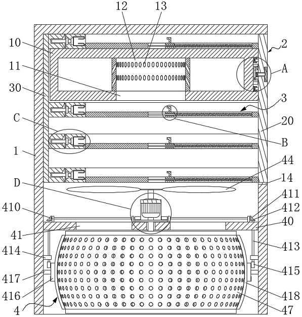
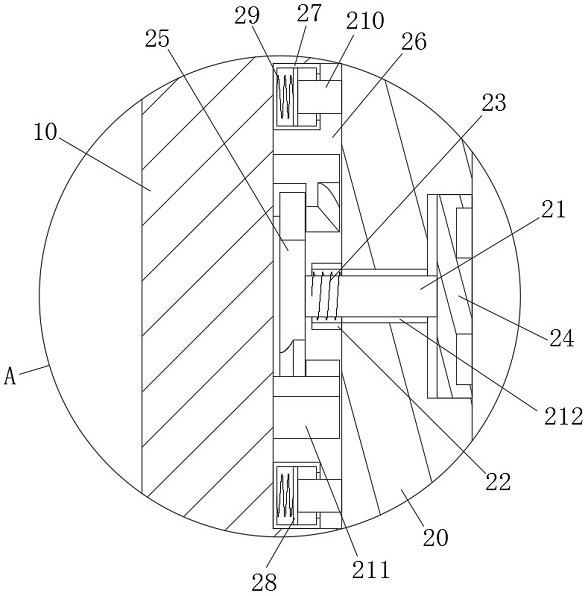
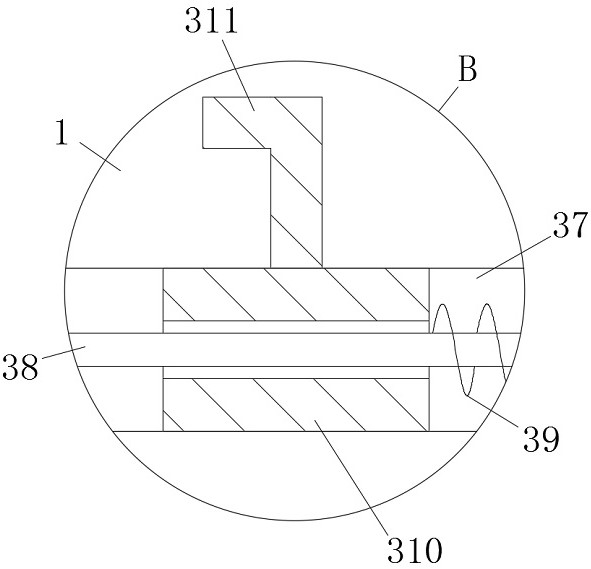
[0028] see Figure 1-11, an embodiment provided by the present invention: an alarm device based on an electromagnetic wave launching base, including a first housing 1, a second housing 10 is fixedly connected to the inner wall of the first housing 1, and the second housing 10 A sealing assembly 2 is installed on the outer wall, and module fixing assemblies 3 are distributedly installed on the sealing assembly 2, and a self-cleaning assembly 4 is installed insi...


PUM


Abstract

The invention discloses an alarm device based on an electromagnetic wave emission base. Comprising a first shell, a sealing assembly, a module fixing assembly, a self-cleaning assembly, a support, a double-shaft motor, fan blades, a first gear, a second connecting rod, a filter element, a second gear, a first connecting shaft, a first supporting block, a third gear, a fourth gear, a second connecting shaft, a second supporting block, a fifth gear, a sixth gear, a third connecting shaft and a cleaning rod. According to the invention, the module fixing assembly is designed and can be used for separately installing each circuit module, so that mutual interference among the modules is reduced, and later maintenance and element replacement are facilitated; the self-cleaning assembly is designed, the filter element can be automatically cleaned, manual maintenance is not needed, and the assembly and the heat dissipation device use the same power source, so that the element cost is reduced, and meanwhile, the size of the device is prevented from being increased; a sealing assembly is designed, and the sealing assembly is convenient to use and can be used for rapid disassembly and assembly of the device.

Description

technical field [0001] The invention relates to the technical field of alarm devices, in particular to an alarm device based on an electromagnetic wave emission base. Background technique [0002] Electromagnetic wave is a kind of transverse wave, which can be used for detection, positioning and communication. A device that detects a human body moving within the range and generates an alarm signal to realize area monitoring. The microwave detector is usually equipped with a microwave generation module, a main control module, a power supply module and a controller module. However, each module is welded The electromagnetic interference generated by the power supply module and the controller module will affect the normal operation of the microwave generation module and bring great inconvenience to the later maintenance and replacement of components; the existing microwave detector is designed with a heat dissipation function , so as to avoid the change of the resistance value ...

Claims


Application Information

Patent Timeline
IPC IPC(8): H05K7/14H05K7/20B01D46/00B01D46/681G08B21/00
CPCH05K7/14H05K7/20172H05K7/20181G08B21/00
Inventor 李菲李刚李楠赵秀梅朱超贤
Owner 北京九九之声科技有限公司
Learn More